The Ministry of Consumer Affairs, Food & Public Distribution has issued a public notice regarding draft rules for Non-Invasive Non-Automated Sphygmomanometers, also known as manual blood pressure monitors. The draft rules, titled the Legal Metrology (General) Fourth Amendment Rules, 2025, propose new standards for the metrological, technical, and safety requirements of these medical devices. The rules are intended to amend the Legal Metrology (General) Rules, 2011, and cover aspects such as maximum permissible errors under various conditions, technical specifications for cuffs and pneumatic systems, and durability requirements. They also define test procedures for model approval and verification. The ministry has placed the draft rules on its website and is seeking comments from all stakeholders, including state legal metrology departments, consumer organizations, and industry associations, by August 30, 2025.
I-9/12/2024-W&M
Government of India
Ministry of Consumer Affairs, Food & Public Distribution
Department of Consumer Affairs
Legal Metrology Division
Krishi Bhawan, New Delhi-01
Dated: 31.07.2025
Subject– Draft Rules for Non-Invasive Non-Automated Sphygmomanometers- comments from stakeholders – reg.
Undersigned is directed to refer to the above mentioned subject and to state that the Draft Rules for Non-Invasive Non-Automated Sphygmomanometers are placed in the website of the Department www.consumeraffairs.nic.in for seeking comments from all stakeholders by 30.08.2025. The comments may be sent to email-ID: dirwm-ca@nic.in/ mk.naik72@gov.in.
(Ashutosh Agarwal)
Director (Legal Metrology)
Ph: 011-23389489
Email: dirwm-ca@nic.in
To:
All concerned (State Legal Metrology Departments, VCOs, Industries and Industry Associations)
[TO BE PUBLISHED IN THE GAZETTE OF INDIA, EXTRAORDINARY, PART II, SECTION 3, SUB-SECTION (i)]
GOVERNMENT OF INDIA
MINISTRY OF CONSUMER AFFAIRS, FOOD AND PUBLIC DISTRIBUTION
(DEPARTMENT OF CONSUMER AFFAIRS)
NOTIFICATION
New Delhi, the ……………. 2025.
GSR……. (E). – In exercise of the powers conferred by sub-section (1) read with clauses (c), (f), (h), (i) and (s) of sub-section (1) of section 52 of the Legal Metrology Act, 2009 (1 of 2010), the Central Government hereby makes the following rules further to amend the Legal Metrology (General) Rules, 2011, namely:-
1. Short title and commencement.– (1) These rules may be called the Legal Metrology (General) Fourth Amendment Rules, 2025.
(2) They shall come into force on the date of their publication in official gazette.
2. In the Legal Metrology (General) Rules, 2011, in the Eight Schedule, for PART VII-A, the following shall be substituted, namely:-
“PART VII- A
NON-INVASIVE NON-AUTOMATED SPHYGMOMANOMETERS
PART 1: METROLOGICAL AND TECHNICAL REQUIREMENTS
1. Scope
This Part specifies general, performance, efficiency and mechanical safety requirements, including test methods for type approval, for non-invasive non-automated sphygmomanometers and their accessories which, by means of an inflatable cuff, are used for the non-invasive measurement of arterial blood pressure.
Included within the scope of this specification are non-invasive non-automated sphygmomanometers with a mechanical or integrated electro-mechanical pressure sensing element and display, used in conjunction with a stethoscope or other manual methods for detecting Korotkoff sounds and for cuff inflation.
2. Terminology
(1) Auscultatory method: The method whereby sounds (known as Korotkoff sounds) are heard or detected (e.g. by a microphone) over an occluded artery as the occluding pressure is slowly released, the appearance of sounds coinciding with the systolic blood pressure and the disappearance of sounds with the diastolic blood pressure.
(2) Bladder: The inflatable component of the cuff.
(3) Cuff: The component of the non-invasive non-automated sphygmomanometer, comprising a bladder and a sleeve, which is wrapped around the limb of the patient
Note: A cuff might comprise a bladder and an inelastic part that encloses the bladder, or have an integral bladder (i.e. the cuff including the bladder are fixed together or are one piece).
(4) Deflation valve: The valve for controlled exhaust of the pneumatic system during measurement
(5) Diastolic blood pressure (value): The minimum value of the arterial blood pressure as a result of relaxation of the systemic ventricle.
Note: Because of hydrostatic effects, this value should be measured with the cuff at the heart level.
(6) Manometer: The instrument used to measure and display pressure.
(7) Non-invasive non-automated sphygmomanometer: The medical measuring instrument used by a trained person for the non-invasive measurement of the arterial blood pressure by utilising an inflatable cuff with a display and used in conjunction with a stethoscope or any other manual methods for estimating blood pressure. Hereafter called sphygmomanometer in this specification.
(8) Non-invasive blood pressure measurement: The indirect measurement of the arterial blood pressure without arterial puncture
(9) Pneumatic system: The system that includes all pressurised and pressure-controlling parts such as cuff, tubing, connectors, valves, transducer and pump
(10) Rapid exhaust valve: The valve for rapidly exhausting the pneumatic system
(11) Sleeve: The essentially inelastic part of the cuff that encloses the bladder
(12) Systolic blood pressure (value): The maximum value of the arterial blood pressure as a result of the contraction of the systemic ventricle
Note: Because of hydrostatic effects, this value should be measured with the cuff at the heart level.
(13) Tamper proofing: The means of preventing the user from gaining easy access to the measuring mechanism of the device.
3. Description of the category of instrument.-
The basic components of a sphygmomanometer are a manometer for measuring and displaying pressure in the bladder and a pneumatic system for applying and releasing pressure in the bladder.
The pneumatic system includes a cuff that can be wrapped around a patient’s limb, tubing, connectors, a valve for deflation (often in combination with rapid exhaust valve), transducers and a hand pump or electromechanical pump. For pressure control, electromechanical components may be used.
Sphygmomanometers typically use either mercury or an aneroid manometer or another mechanical measuring device for the non-invasive measurement of the arterial blood pressure by means of an inflatable cuff.
4. Units of measurement.-
The units used to indicate blood pressure shall be either the kilopascal (kPa) or the millimetre of mercury (mmHg).
5. Metrological requirements.-
(1) Maximum permissible errors of the cuff pressure indication under ambient conditions,-
For any set of conditions within an ambient temperature range from 15 °C to 25 °C and a relative humidity range from 15 % to 85 % for decreasing pressure, the maximum permissible error for the measurement of the cuff pressure at any point of the scale range shall be ±0.4 kPa (±3 mmHg) for sphygmomanometers.
(2) Maximum permissible errors of the cuff pressure indication under storage conditions,-
Sphygmomanometers without electronic components shall maintain the maximum permissible error requirements for the measurement of the cuff pressure specified in sub-paragraph(1) of paragraph 5 after storage for 24 h at a low temperature of −20 °C, followed by additional storage for 24 h at a high temperature of 70 °C and at a relative humidity of 85 % (non-condensing).
Sphygmomanometers with electronic components shall maintain the maximum permissible error requirements for the measurement of the cuff pressure specified in sub-paragraph(1) of paragraph 5 after storage for 24 h at a low temperature of −5 °C, followed by additional storage for 24 h at a high temperature of 50 °C and at a relative humidity of 85 % (non-condensing).
The storage shall occur with the sphygmomanometers unpacked.
(3) Maximum permissible errors of the cuff pressure indication under varying temperature conditions,-
For an ambient temperature range from 10 °C to 40 °C and a relative humidity of 85 % (noncondensing), the difference between the indicated pressure of the manometer of the device to be tested and the corresponding readings of the reference manometer at the relevant temperature value shall not exceed ±0.4 kPa (±3 mmHg) or ±2 % of the reading, whichever is greater.
Note: The requirement of this sub clause does not apply to mercury manometers.
6. Technical requirements.-
(1) Technical requirement for the cuff and bladder,-
The cuff shall contain a bladder. For reusable cuffs the manufacturer shall indicate the method for cleaning in the accompanying documents.
The bladder length should be approximately 0.80 × the circumference of the limb at the midpoint of the intended range of the cuff. The width of the bladder should be at least 0.40 × the circumference of the limb at the midpoint of the intended range of the cuff.
(2) Technical requirements for the pneumatic system,-
(i) Air leakage,-
Air leakage shall not exceed a pressure drop of 0.5 kPa/min (4 mmHg/min).
(ii) Pressure reduction rate,-
The deflation valves in the pneumatic system shall be capable of adjustment to a deflation rate from 0.3 kPa/s to 0.4 kPa/s (2 mmHg/s to 3 mmHg/s).
The deflation valves in the pneumatic system shall be easily adjusted to these values.
(iii) Rapid exhaust,-
During the rapid exhaust of the pneumatic system, with the valve fully opened, the time for the pressure reduction from 34.7 kPa to 2.0 kPa (260 mmHg to 15 mmHg) shall not exceed 10 s.
(3) Technical requirements for the pressure indicating devices,-
(i) Nominal range and measurement range,-
The nominal range shall be equal to the measurement range.
The nominal range for the cuff pressure indication shall extend from 0 kPa to at
least 34.7 kPa (0 mmHg to at least 260 mmHg).
The nominal range for the cuff pressure measurement shall be disclosed in the accompanying document.
The measuring and indication ranges of the cuff pressure shall be equal to the nominal range.
(ii) Analogue indication,-
(a) Scale,-
The scale shall be designed and arranged so that the measuring values can be read clearly and are easily recognised.
Testing shall be carried out by visual inspection.
(b) First scale mark,-
The graduation shall begin with the first scale mark at 0 kPa (0 mmHg).
Testing shall be carried out by visual inspection.
(c) Scale interval,-
The scale interval shall be:
(I) 5 kPa for a scale graduated in kPa;
(II) 2 mmHg for a scale graduated in mmHg.
In the case of a scale graduated in kPa, each fourth scale mark shall be indicated by a greater length and each eighth scale mark shall be numbered. In the case of a scale graduated in mmHg, each fifth scale mark shall be indicated by a greater length and each tenth scale mark shall be numbered. An example of a scale in mmHg is given in Figure 1.
For sphygmomanometers with a manometer with elastic or electro-mechanical sensing elements, no graduation is needed within the range from > 0 kPa to < 2 kPa (> 0 mmHg to < 15 mmHg).
Testing shall be carried out by visual inspection.
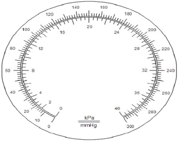
Figure 1 – Example of an aneroid manometer scale
(Division in mmHg without a tolerance zone at zero)
(d) Scale spacing and thickness of the scale marks,-
The distance between adjacent scale marks shall be not less than 1.0 mm. The thickness of the scale marks shall not exceed 20 % of the smallest scale spacing. All scale marks shall be of equal thickness.
(iii) Digital indication,-
The digital scale interval shall be 0.1 kPa (1 mmHg).
If the measured value of a parameter is to be indicated on more than one display, all the displays shall indicate the same numerical value.
Measured numerical values on the display(s), and the symbols defining the units of measurement shall be arranged in such a way so as to avoid misinterpretation.
Numbers and characters shall be clearly legible.
Testing shall be carried out by visual inspection.
(4) Additional technical requirements for mercury manometers,-
(i) Portable devices,-
A portable device shall be provided with an adjusting or locking mechanism to secure it in the specified position of use.
Testing shall be carried out by visual inspection.
(ii) Devices to prevent mercury from being spilled during use and transport,-
A device shall be placed in the tube to prevent mercury from being spilled during use and transport (for example: stopping device, locking device, etc.). This device shall be such that when the pressure in the system drops rapidly from 26.6 kPa to 0 kPa (from 200 mmHg to 0 mmHg), the time taken for the mercury column to fall from 26.6 kPa to 5.3 kPa (from 200 mmHg to 40 mmHg) shall not exceed 1.5 s. This time is known as the “exhaust time”.
(iii) Quality of the mercury,-
(a) The mercury shall have a purity of not less than 99.99 % according to the declaration of the supplier of the mercury.
(b) The mercury shall exhibit a clean meniscus and shall not contain air bubbles.
(iv) Graduation of the mercury tube,-
Graduations shall be permanently marked on the tube containing mercury. If numbered at each fifth scale mark, the numbering shall be alternately on the right- and left-hand side of, and adjacent to, the tube.
Testing shall be carried out by visual inspection.
(5) Additional technical requirements for aneroid manometers,-
(i) Scale mark at zero,-
If a tolerance zone is shown at zero it shall not exceed ±0.4 kPa (±3 mmHg) and shall be clearly marked.
A scale mark at zero shall be indicated.
Note: Graduations within the tolerance zone are optional.
Testing shall be carried out by visual inspection.
(ii) Zero,-
The movement of the elastic sensing element including the pointer shall not be obstructed within 0.8 kPa (6 mmHg) below zero.
Neither the dial nor the pointer shall be adjustable by the user.
Testing shall be carried out by visual inspection.
(iii) Pointer,-
The pointer shall cover between 1/3 and 2/3 of the length of the shortest scale mark of the scale. At the place of indication, it shall be not thicker than the scale mark. The distance between the pointer and the dial shall not exceed 2 mm.
(iv) Hysteresis error,-
The hysteresis error throughout the pressure range shall not exceed the range 0 kPa to 0.5 kPa (0 mmHg to 4 mmHg).
(v) Durability of the manometer,-
The construction of the manometer and the material for the elastic sensing elements shall ensure an adequate stability of the measurement. When elastic sensing elements are used, they shall be aged with respect to pressure and temperature. After 10 000 alternating pressure cycles from 3 kPa (20 mmHg) to full scale, the change in the pressure indication shall be not more than 0.4 kPa (3 mmHg).
(6) Safety requirements,-
(i) Mechanical safety,-
(a) Resistance to vibration and shock for handheld sphygmomanometers,-Sphygmomanometers or their parts shall have adequate mechanical strength when subjected to mechanical stress caused by normal use, pushing, impact, dropping and rough handling.
Wall mounted sphygmomanometers and mercury manometers are exempt from the requirements of this sub clause.
Sphygmomanometers shall function normally following a free fall from a distance d = 25 cm.
A sphygmomanometer that is marked “Shock Resistant” shall function normally following a free fall from a distance d = 1 m.
After testing, the device shall comply with the requirements of sub-paragraph (1) of paragraph 5.
(b) Resistance to vibration and shock for sphygmomanometers used during patient transport,-
Sphygmomanometers or their parts, intended for use during patient transport outside a healthcare facility, shall have adequate mechanical strength when subjected to mechanical stress caused by normal use, pushing, impact, dropping, and rough handling.
After testing, the device shall comply with the requirements of sub-paragraph (1) of paragraph 5.
(c) Sphygmomanometers containing a mercury manometer,-
A sphygmomanometer containing a mercury manometer shall not leak mercury following a free fall from a distance, d = 1 m.
After testing, the device shall comply with the requirements of sub-paragraph (1) of paragraph 5 at a temperature of 20 °C ± 5 °C and ambient humidity.
(ii) Aborting a measurement,-
It shall be possible to abort any blood pressure measurement at any time by activating the manual rapid exhaust valve, which shall be easily accessible.
(iii) Unauthorised access and tamper proofing,-
Means shall be provided to prevent tampering or unauthorised access:
(a) for all sphygmomanometers, any adjustment or function that affects accuracy;
(b) for mercury sphygmomanometers, the separation of reservoir and scale.
Example: Requiring a tool for opening or breaking a seal.
It shall be clear to an operator if tampering or unauthorised access has occurred.
(iv) Electrical Safety,-
Non-automated sphygmomanometers shall comply with the relevant national safety regulations.
(v) Tubing connectors,-
Luer lock and Luer slip connectors shall not be used on non-automated sphygmomanometers so as to avoid any risk of connecting the output of the sphygmomanometer to intervascular fluid systems as air might inadvertently be pumped into a blood vessel.
(vi) Durability of markings,-
The markings shall be removable only with a tool or by appreciable force and shall be sufficiently durable to remain clearly legible during the expected service life of the sphygmomanometer. In considering the durability of the markings, the effect of normal use shall be taken into account.
7. Metrological controls.-
(1) Model approval,-
At least three samples of a new type of sphygmomanometer shall be tested.
The tests to verify conformity to metrological and technical requirements shall be carried out according to Part 2.
(2) Verification,-
At verification, testing can be conducted at any set of climatic conditions within the temperature range from 150 c to 250 c and the relative humidity range from 15 % to 85 %. A climatic chamber is not required.
The requirements of sub-paragraph (1) of paragraph 5 and clause (i) of subparagraph (2) of paragraph 6 shall be fulfilled.
(3) Sealing,-
(i) Control marks shall be put on seals for which corresponding punched screws shall be attached whenever necessary. These seals shall prevent, without destruction of the control marks, the following,-
(a) in the case of mercury manometers: the separation of reservoir and scale;
(b) in the case of all other manometers: the opening of the casing.
(ii) If the construction of the instrument guarantees security against any interference, the metrological control marks or the security marks may be attached in form of labels.
(iii) All seals shall be accessible without using a tool.
(4) Marking of the device,-
(i) Markings required on the indicating device,-
The indicating device of the sphygmomanometer shall be marked with the following information,-
(a) name and/or trademark of the manufacturer;
(b) type of sphygmomanometer;
(c) units of measurement (kPa and/or mmHg), positioned close to the displayed values;
(d) measurement range;
(e) model approval number;
(f) serial number;
(g) year of fabrication;
(h) country of origin;
(i) information on the mercury content (required for mercury manometers).
(ii) Markings required on the cuff,-
The cuff of the sphygmomanometer shall be marked with the following information,-
(a) limb circumference for which it is appropriate;
(b) marking of the limb circumference indication range;
(c) centre of the bladder, indicating the correct position for the cuff over the artery.
Testing shall be carried out by visual inspection.
(5) Manufacturer’s information,-
(i) Information supplied by the manufacturer shall comply with the specifications and requirements given in this Specification.
(ii) The manufacturer’s instruction manual shall contain the following information,-
(a) Explanation of the operating procedures which are important for correct application (such as the selection of the appropriate cuff size, positioning of the cuff at the heart level and adjustment of the pressure reduction rate);
(b) methods for cleaning reusable cuffs;
(c) if the bladder is removable, the method for ensuring the correct repositioning of the bladder in the cuff;
(d) nature and frequency of the maintenance required to ensure that the device operates correctly and safely at all times;
(e) disclosure that applicable national or regional metrological laws and regulations shall be considered;
(f) detailed instructions for the safe handling of mercury ;
(g) list of all components belonging to the pressure measuring system, including accessories;
(h) remarks on the environmental or operational factors which may affect the performance (e.g. electromagnetic fields, arrythmia);
(j) specification of the rated voltage, if applicable;
(k) specification of the intended power source, if applicable;
(l) measurement range;
(m) operating and storage temperature, and humidity ranges;
(n) warm-up time, if applicable;
(o) description of all symbols, abbreviations and error codes used on the instrument; and
(p) name and address of manufacturer.
Testing shall be carried out by visual inspection
PART 2: TEST PROCEDURES
1. Test for maximum permissible errors of the cuff pressure indication.-
(1) Apparatus,-
The apparatus consists of the following:-
(i) rigid metal vessel with a capacity of 500 ml ± 25 ml;
(ii) calibrated reference manometer with maximum permissible error within ±0.1 kPa (±0.8 mmHg);
(iii) pressure generator, e.g. ball pump (hand pump) with a deflation valve;
(iv) T-piece connectors;
(v) hoses with an overall length of no more than 600 mm.
(2) Procedure,-
Replace the cuff with the vessel. Connect both the calibrated reference manometer and the manometer of the device to be tested to the pneumatic system by means of a T-piece connector and hoses (see Figure 1). After disabling the electromechanical pump (if fitted), connect the pressure generator into the pressure system by means of another T-piece connector. Carry out the test in pressure steps of not more than 6.7 kPa (50 mmHg) between 0 kPa (0 mmHg) and the maximum pressure of the scale range.
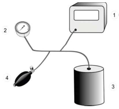
1 – Reference manometer; 2 – Manometer of the device to be tested;
3 – Metal vessel; 4 – Pressure generator
Figure 1 – Measurement system for determining the limits of error of the cuff pressure indication
(3) Expression of results,-
Express the results as the differences between the indicated pressure of the manometer of the device to be tested and the corresponding readings of the reference manometer.
2. Test for maximum permissible errors of the cuff pressure indication under varying temperature conditions.-
(1) Apparatus,-
The apparatus consists of the following:-
(i) apparatus as specified in sub-paragraph(1) of paragraph 1 of Part 2; plus
(ii) a climatic chamber, non-uniformity of temperature within ±1 °C, instability of temperature within ±1 °C, non-uniformity of relative humidity within ±5 %, instability of relative humidity within ±5 %.
(2) Procedure,-
Replace the cuff with the vessel.
Connect both the calibrated reference manometer and the manometer of the device to be tested to the pneumatic system by means of a T-piece connector (see Figure 2). After disabling the electromechanical pump (if fitted), connect the additional pressure generator into the pneumatic system by means of another T-piece connector.
For each of the following combinations of temperature and humidity, condition the device for at least 3 h in the climatic chamber to allow the device to reach steady conditions:
(i) 10°C ambient temperature, 85 % relative humidity (non-condensing);
(ii) 20°C ambient temperature, 85 % relative humidity (non-condensing);
(iii) 40°C ambient temperature, 85 % relative humidity (non-condensing). Carry out the test of the cuff pressure indication as described in sub-paragraph (2) of paragraph 1 of Part 2 for each of the combinations of temperature and humidity mentioned above.
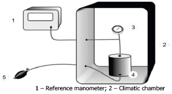
1 – Reference manometer; 2 – Climatic chamber
3 – Manometer of the device to be tested; 4 – Metal vessel
5 – Pressure generator
Figure 2 – Measurement system for determining the influence of temperature
(3) Expression of results,-
Express the results as the differences between the indicated pressure of the manometer of the device to be tested and the corresponding readings of the reference manometer at the relevant temperature value.
3. Test for maximum permissible error of the cuff pressure indication under storage conditions.-
(1) Apparatus,-
The apparatus is as specified in sub-paragraph (1) of paragraph 2 of Part 2
(2) Procedure,-
Replace the cuff with the vessel. Connect both the calibrated reference manometer and the manometer of the device to be tested to the pneumatic system by means of a T-piece connector (see Figure 2). After disabling the electro-mechanical pump (if fitted), connect the additional pressure generator into the pneumatic system by means of another T-piece connector.
Unpack the non-automated sphygmomanometer and store the instrument under test conditions as specified in sub clause 5(2) of Part 1.
Note: This is one procedure and not two separate ones.
After at least one hour at a temperature of 20 °C ± 5 °C and 60 % relative humidity, carry out the test according the procedure in sub-paragraph(2) of paragraph 1 of Part 2.
(3) Expression of results,-
Express the results as the differences between the indicated pressure of the manometer of the device to be tested and the corresponding readings of the reference manometer.
4. Test for air leakage of the pneumatic system.-
To comply with the requirement of clause(i) of sub-paragraph(2) of paragraph 6 of Part 1, the following test shall be performed:-
(1) Apparatus,-
The apparatus consists of the following:
(i) rigid metal cylinder of an appropriate size;
(ii) pressure generator, e.g. Ball pump (hand pump) with a deflation valve;
(iii) time measuring device with a maximum permissible error of 0.1 s.
(2) Procedure,-
Wrap the cuff around the cylinder of an appropriate size, such that the internal circumference of the applied cuff exceeds the circumference cylinder by (7 ± 2) %.
Note: Electro-mechanical pumps which are part of the device may be used for the test.
Carry out the test over the whole measurement range at at least three equally spaced pressure steps (e.g. 6.7 kPa (50 mmHg), 20.0 kPa (150 mmHg), and 33.3 kPa (250 mmHg)). Test the air leakage over a period of 5 min and determine the measured value from this.
(3) Expression of results,-
Express the air leakage as the rate of the pressure loss per minute.
5. Test for pressure reduction rate for deflation valves.-
To comply with the requirement of clause (ii) of sub-paragraph (2) of paragraph 6 of Part 1, the following test shall be performed:-
(1) Apparatus,-
The apparatus consists of the following:
(i) T-piece connector;
(ii) calibrated reference manometer with signal output and maximum permissible error within ±0.1 kPa (±0.8 mmHg);
(iii) artificial limbs (see notes under paragraph sub-paragraph(2) of paragraph 5 of Part 2);
(iv) recording unit, which can record the output of the calibrated reference manometer,giving deflation rate in kPa/s or mmHg/s.
(2) Procedure,-
Measure the pressure reduction rate either on human limbs or artificial limbs.
Note 1: The intention is to use artificial limbs, but measurements performed with
human volunteers are acceptable.
Note 2: It is intended that the properties of the artificial limbs reflect some elastic
properties of human limbs.
Because the cuff deflation rate may be influenced by the way in which the cuff is applied, the cuff should be applied and removed for each of at least ten repeated measurements, on at least two different limb sizes. These two limb sizes should be equal to the upper and lower limits of the limb circumferences for which a particular size of cuff is recommended to be used. Resetting the deflation valve is permitted during the test.
Connect the calibrated reference manometer to the cuff by means of a T-piece connector. Connect the output of the calibrated reference manometer to the recording unit.
Plot the pressure reduction in the form of a pressure curve as a function of time.
(3) Expression of results,-
Determine the rate of pressure reduction by graphical evaluation (by drawing tangents) at the pressure values of 8.0 kPa (60 mmHg), 16.0 kPa (120 mmHg) and 24.0 kPa (180 mmHg). The pressure reduction rate is the mean value calculated separately for these three pressure values and for the various limb circumferences.
6. Test for rapid exhaust.-
To comply with the requirement of clause(iii) of sub-paragraph(2) of paragraph 6 of Part 1, the following test shall be performed:-
(1) Apparatus,-
The apparatus consists of the following:-
(i) rigid metal cylinder of an appropriate size (see sub-paragraph(1) of paragraph 6 of Part 1);
(ii) pressure generator if necessary, e.g. ball pump (hand pump) with a deflation valve;
(iii) T-piece connector;
(iv) time measuring device with a maximum permissible error of 0.1 s.
(2) Procedure,-
Carry out the test with the vessel in place of the cuff.
Connect the calibrated reference manometer to the pneumatic system by means of a T-piece connector.
Inflate to the maximum pressure and open the rapid exhaust valve. Measure the time between the pressure values specified in clause (iii) of sub-paragraph (2) of paragraph 6 of Part 1.
(3) Expression of results,-
Express the result as the time for the pressure reduction from 34.7 kPa to 2.0 kPa (260 mmHg to 15 mmHg).
7. Test for scale spacing and thickness of the scale marks.-
To comply with the requirement of sub-clause(d) of clause(iii) of sub-paragraph(3) of paragraph 6 of Part 1, the following test shall be performed,-
(1) Apparatus,-
The apparatus consists of the following:-
(i) scaled magnifying lens or similar device.
(2) Procedure,-
Determine the thickness of the scale marks and the scale spacing in at least three different areas of the scale using the scaled magnifying lens.
8. Test for security against mercury losses.-
To comply with the requirement of clause (ii) of sub-paragraph (4) of paragraph 6 of Part 1, the following test shall be performed,-
(1) Apparatus,-
The apparatus consists of the following:-
(i) collecting vessel of an adequate size;
(ii) calibrated reference manometer, with a nominal range up to at least 53.2 kPa (400 mmHg) and maximum permissible error within ±0.13 kPa (±1.0 mmHg);
(iii) T-piece connector;
(iv) pressure generator, e.g. ball pump (hand pump) with a deflation valve;
(v) time measuring device with a maximum permissible error of 0.1 s.
(2) Procedure and evaluation,-
Place the sphygmomanometer to be tested in the collecting vessel. Connect the pressure generator and a T-piece connector attached to a calibrated reference manometer directly to the hose leading to the mercury reservoir. Use the pressure generator to raise the pressure in the manometer to 13.3 kPa (100 mmHg) greater than the maximum indicated scale reading on the test manometer. Maintain this pressure for
5 s and then release the pressure in the system.
Check that no mercury has spilled.
9. Test for the influence of the mercury stopping device.-
To comply with the requirement of clause (ii) of sub-paragraph (4) of paragraph 6 of Part 1, the following test shall be performed,-
(1) Apparatus,-
The apparatus consists of the following:-
(i) pressure generator, e.g. ball pump (hand pump) with a deflation valve
(ii) time measuring device with a maximum permissible error of 0.1 s
(2) Procedure and evaluation,-
Connect the pressure generator directly to the hose leading to the mercury reservoir, i.e. without connecting a cuff. When a gauge pressure of more than 26.6 kPa (200 mmHg) has been reached, occlude the tube and remove the pressure generator.
After removing the occlusion from the tube, measure the time taken for the mercury column to fall from the 26.6 kPa (200 mmHg) mark to the 5.3 kPa (40 mmHg) mark.
Check that the exhaust time does not exceed 1.5 s.
10. Test for the hysteresis error of aneroid manometer.-
To comply with the requirement of clause (iv) of sub-paragraph (5) of paragraph 6 of Part 1, the following test shall be performed,-
(1) Apparatus,-
The apparatus consists of the following:-
(i) rigid metal vessel, with a capacity of 500 ml ± 25 ml;
(ii) calibrated reference manometer with a maximum permissible error within ±0.1 kPa (±0.8 mmHg);
(iii) pressure generator, e.g. ball pump (hand pump) with a deflation valve;
(iv) T-piece connectors;
(v) time measuring device with a maximum permissible error of 0.1 s.
(2) Procedure,-
Replace the cuff with the vessel. Connect the calibrated reference manometer to the pneumatic system by means of a T-piece connector. After disabling the electromechanical pump (if fitted), connect the additional pressure generator into the pneumatic system by means of another T-piece connector.
Test the device with increasing pressure steps of not more than 6.7 kPa (50 mmHg) to the scale maximum, at which point hold the pressure for 5 min and then decrease it by the same steps. Do not tap on the manometer housing to reduce the friction to move the pointer.
Disconnect the calibrated reference manometer during the 5 min at maximum pressure, if it has elastic sensing elements.
(3) Expression of results,-
Express the results as the difference between the indicated values on the manometer at the same test pressure steps when increasing the pressure and when decreasing the pressure.
11. Test for durability of aneroid manometers,-
To comply with the requirement of clause (v) of sub-paragraph (5) of paragraph 6 of Part 1, the following test shall be performed,-
(1) Apparatus,-
The apparatus consists of the following:-
(i) alternating pressure generator, which generates a sinusoidal pressure variation between 3 kPa and 30 kPa (20 mmHg and 220 mmHg) at a maximum rate of 60 cycles per minute.
(2) Procedure,-
Carry out the procedure specified in paragraph 1 of Part 2.
Connect the aneroid manometer directly to the alternating pressure generator and perform 10 000 alternating pressure cycles. A full-scale cycle is a pressure change from 20 mmHg to full scale, and then back to 20 mmHg.
One hour after the stress test, carry out the procedure as specified in paragraph 1 of Part 2 at the same test pressure levels as before the stress test.
(3) Expression of results,-
Express the results as the changes, Δphyst, between the indicated values on the manometer at the same test pressure steps on deflation, pdown, and on inflation, pup, using the equation Δphyst = pdown − pup.
12. Test for mechanical safety.-
To comply with the requirement of clause (i) of sub-paragraph (6) of paragraph 6 of Part 1, the following test shall be performed,-
(1) Resistance to vibration and shock for handheld sphygmomanometers,-
Sphygmomanometers shall function normally following a free fall from a distance d = 25 cm.
A sphygmomanometer that is marked “Shock Resistant” shall function normally following a free fall from a distance d = 1 m.
Allow the sphygmomanometer to fall freely six times (once on each side) from a height of distance d = 1 m onto a 50 mm ± 5 mm thick hardwood (hardwood density > 600 kg/m3) board lying flat on a concrete or a similar rigid base.
(2) Resistance to vibration and shock for sphygmomanometers used during patient transport,-
(i) Shock:
(a) peak acceleration: 1 000 m/s2 (102 g);
(b) duration: 6 ms;
(c) pulse shape: Half sine;
(d) number of shocks: three shocks per direction per axis (18 total).
(ii) Broad-band random vibration:
(a) frequency range: 10 Hz to 2 000 Hz;
(b) resolution: 10 Hz;
(c) acceleration amplitude:
10 Hz to 100 Hz: 5.0 (m/s2)2/Hz;
100 Hz to 200 Hz: -7 db/octave;
200 Hz to 2 000 Hz: 1.0 (m/s2)2/Hz;
(d) duration: 30 min on each perpendicular axis (three total).
(3) Sphygmomanometers containing a mercury manometer,-
Allow the sphygmomanometer to fall freely six times (once on each side) from a height of distance d = 1 m onto a 50 mm ± 5 mm thick hardwood (hardwood density > 600 kg/m3) board lying flat on a concrete or a similar rigid base. Care should be taken while testing to ensure that there is no escape of mercury into the environment should the sphygmomanometer under test fail. After the test, visually inspect to check that there is no leakage of mercury from the manometer of the sphygmomanometer.
13. Test for durability of markings.-
To comply with the requirement of sub-paragraph (7) of paragraph 6 of Part 1, the following test shall be performed,-
Check compliance by inspection and the following tests.
After all the other tests of this specification have been performed:-
(1) markings are rubbed by hand, without undue pressure, first for 15 s with a cloth soaked with distilled water, then for 15 s with a cloth soaked with methylated spirits and then for 15 s with a cloth soaked with isopropyl alcohol;
(2) adhesive labels shall not have worked loose or become curled at the edges
[No. I-9/12/2024-W&M]
(Anupam Mishra)
Joint Secretary to the Government of India
Note:- The principal rules were published in the Gazette of India, Extraordinary, Part II, section 3, sub-section (i) Vide notification number G.S.R.71(E), dated the 7th February, 2011 and was last amended vide notification number G.S.R 242(E), dated the 21st April, 2025.