I-9/8/2024-W&M
Government of India
Ministry of Consumer Affairs, Food & Public Distribution
Department of Consumer Affairs
Legal Metrology Division
Krishi Bhawan, New Delhi-01
Dated: 30.5.2024
Subject- Draft Rules on moisture meters for cereal grains and oilseeds for comments from stakeholders – reg.
Undersigned is directed to refer to the above mentioned subject and to state that the Draft Rules on moisture meters for cereal grains and oilseeds, are placed in the website of the Department www.consumeraffairs.nic.in for seeking comments from all stakeholders by 29.06.2024. The comments may be sent to email-ID: dirwm-ca@nic.in/ ashutosh.agarwal13@nic.in/ mk.naik72@gov.in.
(Ashutosh Agarwal)
Director (Legal Metrology)
Ph: 011-23389489
Email: ashutosh.agarwal13@nic.in
To:
All concerned
GOVERNMENT OF INDIA
MINISTRY OF CONSUMER AFFAIRS, FOODAND PUBLIC DISTRIBUTION
(DEPARTMENT OF CONSUMER AFFAIRS)
New Delhi, the …………………… 2024
NOTIFICATION
GSR ………….. In exercise of the powers conferred by sub-section (1) read with clauses (c), (f), (h), (i) and (s) of sub-section (2) of section 52 of the Legal Metrology Act 2009, (1 of 2010), the Central Government hereby makes the following rules, namely:-
1. Short title and commencement
(1) These rules may be called the Legal Metrology (General) (Amendment) Rules, 2024.
(2) They shall come into force from the date of publication of this notification in the Official Gazette, as follows:
(i) All the Moisture meters for cereal grains and oilseeds shall be verified and stamped before sale/ putting into use;
(ii) All the Moisture meters for cereal grains and oilseeds which are already in use at the time of publication of this notification shall be verified and stamped within one year.
2. In the index of the Schedule of the Legal Metrology (General) Rules, 2011 under the Eight Schedule after Part XI, the entries “Part XII”, “Moisture meters for cereal grains and oilseeds” shall be inserted.
3. In the Legal Metrology (General) Rules, 2011, (herein after referred to as the said rules), under the Eight Schedule the Part XII and the entries made thereunder, the following shall be inserted, namely. –
PART (XII) – MOISTURE METERS FOR CEREAL GRAINS
AND OILSEEDS
Part 1: Metrological and technical requirements
1. Scope
(1) Requirements and tests
This Part specifies the metrological and technical requirements, test methods and maximum permissible errors for the type approval of grain moisture meters used in commercial transactions of cereal grains and oilseeds.
(2) Indications
This specification applies to digitally indicating automatic grain moisture meters that directly display moisture content.
(3) Applications
This specification applies to moisture measuring instruments that estimate moisture based on indirect physical means (e.g. electrical or optical sensing). Drying methods or any other direct moisture measurement technology are not specifically covered, but may qualify if they perform to the requirements of this specification
(4) Type of measuring instrument
This specification applies to grain moisture meters that measure the moisture content of a fixed representative-size grain sample. It does not apply to devices used for in-motion measurement of grain or seed moisture content.
(5) New technology
This specification specifies instrument performance specifications and is not intended to preclude the application of new technologies to grain moisture measurement.
2. Terminology
(1) Adjustment
Set of operations carried out on a measuring system so that it provides prescribed indications corresponding to given values of a quantity to be measured Additional note: A change in the value of any of a device’s sealable calibration parameters or sealable configuration parameters.
(2) Accuracy; measurement accuracy
Closeness of agreement between a measured quantity value and a true quantity value of the measurand.
Note 1: The concept of ‘measurement accuracy’ is not a quantity and is not given a numerical quantity value. A measurement is said to be more accurate when it offers a smaller measurement error.
Note 2: The term “measurement accuracy” should not be used for measurement trueness and the term “measurement precision” should not be used for “measurement accuracy”, which, however, is related to both concepts.
Note 3: ‘Measurement accuracy’ is sometimes understood as closeness of agreement between measured quantity values that are being attributed to the measurand.
(3) Calibration
Operation that, under specified conditions, in a first step, establishes a relation between the quantity values with measurement uncertainties provided by measurement standards and corresponding indications with associated measurement uncertainties and, in a second step, uses this information to establish a relation for obtaining a measurement result from an indication
Note 1: A calibration may be expressed by a statement, calibration function, calibration diagram, calibration curve, or calibration table. In some cases, it may consist of an additive or multiplicative correction of the indication with associated measurement uncertainty.
Note 2: Calibration should not be confused with adjustment of a measuring system, often mistakenly called “self-calibration”, nor with verification of calibration.
Note 3: Often, the first step alone in the above definition is perceived as being calibration.
(4) Certified reference material; CRM
Reference material, accompanied by documentation issued by an authoritative body and providing one or more specified property values with associated uncertainties and traceability, using valid procedures
(5) Maximum permissible measurement error (MPE) (maximum permissible error, limit of error)
Extreme value of measurement error, with respect to a known reference quantity value, permitted by specifications or regulations for a given measurement, measuring instrument, or measuring system
Note 1: Usually the term “maximum permissible errors” or “limits of error” are used, where there are two extreme values.
Note 2: The term “tolerance” should not be used to designate “maximum permissible error”.
Additional note: The MPEs in 4(4) (ii) of this specification are errors associated with a meter in use in the market place. The errors for the test procedures are based on 4(4) (i).
(6) Measurement error (error of measurement, error)
Measured quantity value minus a reference quantity value Note 1: The concept of ‘measurement error’ can be used both
(i) When there is a single reference quantity value to refer to, which occurs if a calibration is made by means of a measurement standard with a measured quantity value having a negligible measurement uncertainty or if a conventional quantity value is given, in which case the measurement error is known, and true quantity values of negligible range, in which case the measurement error is not known, and
(ii) If a measurand is supposed to be represented by a unique true quantity value or a set of true quality values of negligible range, in which case the measurement error is not known.
Note 2: Measurement error should not be confused with production error or mistake.
(7) Measurement repeatability (repeatability)
Measurement precision under a set of repeatability conditions of measurement
(8) Measurement reproducibility (reproducibility)
Measurement precision under reproducibility conditions of measurement Additional note: In this specification, the reproducibility of measurements between units of the same type of instrument under reference conditions is assessed by the standard deviation of differences (SDD1). The reproducibility of measurements from one instrument when select influence factors are varied is assessed by the magnitude of the error shift or fault.
(9) Rated operating condition
Operating condition that must be fulfilled during measurement in order that a measuring instrument or measuring system performs as designed
Note: Rated operating conditions generally specify intervals of values for a quantity being measured and for any influence quantity.
(10) Reference condition
Operating condition prescribed for evaluating the performance of a measuring instrument or measuring system or for comparison of measurement results
Note 1: Reference conditions specify intervals of values of the measurand and influence quantities.
(11) Reference quantity value; reference value
Quantity value used as a basis for comparison with values of quantities of the same kind
(12) Repeatability condition of measurement (repeatability condition)
Condition of measurement, out of a set of conditions that includes the same measurement procedure, same operators, same measuring system, same operating conditions and same location, and replicate measurements on the same or similar objects over a short period of time
Note 1: A condition of measurement is a repeatability condition only with respect to a specified set of repeatability conditions.
Note 2: In chemistry, the term “intra-serial precision condition of measurement” is sometimes used to designate this concept.
(13) Reproducibility condition of measurement (reproducibility condition)
Condition of measurement, out of a set of conditions that includes different locations, operators, measuring systems, and replicate measurements on the same or similar objects
Note 1: Different measuring systems may use different measurement procedures. Note 2: A specification should give the conditions changed and unchanged, to the extent practical.
(14) Type approval
Decision of legal relevance, based on the review of the type evaluation report that the type of a measuring instrument complies with the relevant statutory requirements and results in the issuance of the type approval certificate
(15) Type (pattern) evaluation
Conformity assessment procedure on one or more specimens of an identified type (pattern) of measuring instruments which results in an evaluation report and/or an evaluation certificate
Note: ‘Pattern’ is used in legal metrology with the same meaning as ‘type’; in the entries below, only ‘type’ is used.
(16) Verification of a measuring instrument
Conformity assessment procedure (other than type evaluation) which results in the affixing of a verification mark and/or issuing of a verification certificate
(17) Audit trail
Continuous data file containing a time stamped information record of events, e.g. changes in the values of parameters of a device or software updates, or other activities that are legally relevant and which may influence the metrological characteristics
(18) Cryptographic means
Encryption of data by the sender (storing or transmitting program) and description by the receiver (reading program) with the purpose of hiding information from unauthorized persons. Electronic signing of data with the purpose of enabling the receiver or user of the data to verify the origin of the data, i.e. to prove their authenticity
(19) Fault
[With reference to a certified measurement standard]: difference between the error of indication [during or after exposure to a disturbance] and the mean intrinsic error of a measuring instrument
Note 1: Principally, a fault is the result of an undesired change of data contained in or flowing through an electronic measuring instrument.
Note 2: From the definition it follows that a “fault” is a numerical value which is expressed either in a unit of measurement or as a relative value.
Additional note: If a certified measurement standard is not used, a fault is the difference between a single indication during or after a disturbance, and the mean indication at reference conditions prior to test.
(20) Intrinsic error
Error of a measuring instrument, determined under reference conditions
(21) Legally relevant
Software/hardware/data or part of the software/hardware/data of a measuring instrument which interferes with properties regulated by legal metrology, e.g. the accuracy of the measurement or the correct functioning of the measuring instrument
(22) Open network
Network of arbitrary participants (electronic devices with arbitrary functions). The number, identity and location of a participant can be dynamic and unknown to the other participants. This is in contrast to a closed network which is a network of a fixed number of participants with a known identity functionality and location
(23) Universal computer
Computer that is not constructed for a specific purpose but that can be adapted to the metrological task by software. In general this software is founded on an operating system that permits loading and execution of software for specific purposes
(24) (Software) validation
Confirmation by examination and provision of objective evidence (i.e. information that can be proved true, based on facts obtained from observations, measurement, test, etc.) that the particular requirements for the specific intended use are fulfilled. In the present case the related requirements are those of this specification.
(25) Accuracy of a grain moisture calibration; calibration accuracy
Performance characteristic of a calibration assessed at reference conditions Additional note: The assessment requires calculation of 5, the bias over a set of test samples or the ‘calibration bias’, and the standard deviation of the difference (SDD) between the meter and the reference method for each of the 2 % moisture intervals which is the standard deviation of measurement errors from the same sample set. Refer to, 1(2) of Part 2 for the calculation of 5 and SDD from measured values. The limiting values for 5 and SDD in column 2, Table 4(4)(i) shall be observed in order to deem a calibration as sufficiently accurate.
(26) Average error shift
Algebraic mean of error shift values calculated from samples of the same grain type with different moisture levels. The resulting ‘average’ value is indicative of the average variation over the encompassed measurement range, as opposed to the variation in measured values at one point of the range
Note: In this specification, reference to a resulting ‘mean’ value is reserved for the mean of replicated measurements, i.e. the mean of measured values on the same test sample (usually taken under repeatability conditions).
(27) Auxiliary battery
Battery that is
(i) Mounted in, or connected to, an instrument that can also be powered by the mains power, and
(ii) Capable of completely powering the instrument for a reasonable period of time.
(28) back-up battery
Battery intended to power specific functions of an instrument in the absence of the primary power supply. Example: to preserve stored data
(29) Calibration equation; calibration
Set of calibration coefficients for one type of grain to convert raw instrument data into a moisture content measurement
(30) Checking facility
Facility incorporated in a measuring instrument and which enables significant faults to be detected and acted upon
Note: “Acted upon” refers to any adequate response by the measuring instrument (luminous signal, acoustic signal, prevention of the measurement process, etc.).
(31) enabling/inhibiting sealable hardware
physically sealable hardware, such as a two-position switch, located on a remotely configurable device, that enables and inhibits the capability to receive adjustment values or changes to sealable configuration parameters from a remote device
(32) Error shift
With reference to a certified measurement standard: difference between the mean error of indication while one or more influence quantities are varied within the rated operating conditions and the mean intrinsic error of a measuring instrument. See 4(4)(i) for the error shifts associated with grain moisture meter testing
Note: If a certified measurement standard is not used, the error shift is the difference between two measured values: the indication under rated operating conditions and the mean indication at reference conditions prior to test.
(33) Grain
For the purpose of this specification grain means oil seeds, pulses and cereal grains
(34) Integrity of programs, data or parameters
Assurance that the programs, data or parameters have not been subjected to any unauthorized or unintended changes during their use, transfer, storage, repair or maintenance
(35) Moisture content wet-basis
Ratio of moisture to the total mass of the grain sample
(36) Moisture meter
Instrument that measures a parameter (electrical, optical, etc.) to predict the moisture content of a grain within specified error limits
(37) Sample temperature sensitivity (STS)
Measurement variation (relative to the moisture values obtained at reference conditions) resulting from the range of grain sample temperatures permitted in commercial measurements
Note: STS is controlled in approved moisture calibrations. During assessment, a limit is placed on the value of the average error shift caused by allowable temperature variations.
(38) Significant fault
Fault greater than the value specified in this specification (see 4(4) (i))
Note: The relevant specification may specify that the following faults are not significant, even when they exceed the value defined in 4(4) (i):
(i) Faults arising from simultaneous and mutually independent causes (e.g. EM fields and discharges) originating in a measuring instrument or in its checking facilities;
(ii) Faults implying the impossibility to perform any measurement;
(iii) Transitory faults being momentary variations in the indication, which cannot be interpreted, memorized or transmitted as a measurement result;
(iv) Faults giving rise to variations in the measurement result that are serious enough to be noticed by all those interested in the measurement result; the relevant specification may specify the nature of these variations.
(39) Abbreviations and acronyms
| AC | Alternating Current |
| DC | Direct Current |
| EM | Electromagnetic |
| EMC | Electromagnetic Compatibility |
| e.m.f. | Electromotive Force |
| ESD | Electrostatic Discharge |
| EUT | Equipment Under Test |
| M | Reference Moisture |
| MPE | Maximum Permissible Error |
| RF | Radio Frequency |
| RH | Relative Humidity |
| SD | Standard Deviation [See Part 2, clause 1(3)] |
| SDD | Standard Deviation of Differences [See Part 2, clause 1(2)] |
| STS | Sample Temperature Sensitivity [See Part 2, clause 3] |
| t | Actual Temperature During a Test |
| tref | Reference Temperature During a Test |
| Δt | Magnitude of the Temperature Difference Between a Sample and an Instrument at Tt Ref |
| tC | Minimum Environmental Temperature Specified in This Specification for Type Testing |
| tH | Maximum Environmental Temperature Specified in This Specification for Type Testing |
| y̅ | Average of the Difference Between Meter Reading and Reference Method |
3. Units of measurement
(1) Moisture content
The unit of measurement for the moisture content of a grain sample, which is to be displayed on a moisture meter, is the % moisture by mass. Reference moisture (M) is expressed as the percentage mass loss of the sample as determined by the reference method. The equation below represents wet-basis moisture content:
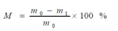
Where m0 is the original mass of the sample and m1 is the final mass of the sample.
4. Metrological requirements
(1) Influence quantities
(i) Reference conditions
(a) Ambient temperature: 20 °C to 27 °C
(b) Relative humidity: 30 % to 70 %
(c) Atmospheric pressure: 86 kPa to 106 kPa
(d) Power voltage: nominal mains or test voltage, Vnom or Unom
(e) Power frequency: nominal frequency, Fnom
(f) Instrument tilt position: level at 0º ± 0.1º
Note: During each test, the tref and RHref shall not vary by more than ±2 °C and ±10 % respectively within the allowable ranges.
(ii) Disturbance test ranges
(a) AC mains voltage dips, short interruptions and voltage variations: reduction to 0 % (0.5 cycle), reduction to 0 % (1 cycle), reduction to 70 % (25 / 30(1) cycles), reduction to 0 % (250 / 300(1) cycles).
(b) Bursts (transients) on AC mains: Amplitude 1 kV, repetition rate 5 kHz
(c) Radiated radio-frequency fields, electromagnetic fields: 26 MHz – 2 GHz, 10 V/m
(d) Conducted radio-frequency fields: 0.15 MHz – 80(2) MHz, 10 V (e.m.f.)
(e) Electrostatic discharge – direct application: Up to 6 kV contact discharge
(f) Electrostatic discharge – indirect application: Up to 8 kV air discharge
(g) Storage temperature (extreme shipping conditions): –20 ºC to 50 ºC or greater as specified by the national responsible body.
Note 1: The cycle counts apply for 50 Hz / 60 Hz respectively
Note 2: Testing up to 26 MHz is permitted. Refer to Part 2, clause 3(5) (iv) for conditions.
(2) Rated operating conditions
Measuring instruments shall be designed and manufactured such that their errors do not exceed the MPEs for initial verification as defined in 4(4)(ii) when operated within the operating conditions defined below:
(i) Ambient temperature: 10 °C to 30 °C (1)
(ii) Relative humidity: up to 85 % no condensation
(iii) Atmospheric pressure: 86 kPa to 106 kPa
(iv) Power voltage: –15 % to +10 % of mains or test voltage
(v) Power frequency: nominal frequency, Fnom
(vi) Instrument tilt position: 5 % or maximum allowable on level indicator where indicator is present
(vii) Grain sample temperature: 2 °C to 40 °C (2)
(viii) Sample and instrument temperature differential: 10 °C (3)
(ix) Grain sample moisture range: Specified by the manufacturer (See 5(1))
(1) This is the minimum range. The manufacturer may specify a wider range (see 4(6)).
(2) This is the minimum grain sample temperature range. The manufacturer shall specify the temperature range for each grain or seed for which the meter is to be used (see 4(7)).
(3) This is the minimum differential. The manufacturer may specify a larger differential. (see 4(7)).
(3) Reference method
An air oven method is the most common rapid reference method for grain moisture determination. National air oven methods vary widely in procedures and results, but all are based on heating a known mass sample for a prescribed period of time (or until the sample no longer loses mass) at a prescribed temperature and measuring the loss of mass. The amount of mass lost is assumed to be the amount of water that was present in the sample. Unfortunately, water is not the only constituent that is driven off by heating. In the “ideal” oven method, the heating times and temperatures would be set so that the amount of non-aqueous material driven off is approximately equal to the amount of water that remains after drying. Those parameters are determined by comparing the air oven method to other more basic (and more difficult) methods such as the phosphorous pentoxide (P2O5) method or the Karl Fischer method. Most air oven methods require hours or days to complete.
(4) Maximum permissible errors (MPEs)
For type evaluation the maximum permissible error for grain moisture meters as a function of the grain type and moisture content is half the MPE that is applied at verification or in-field inspection: The maximum value within a given interval of moisture content shall be used as the reference moisture content for all requirements in calibration/testing. For consistency of application in testing laboratories in different countries, it is recommended that each of the 2 % moisture intervals should begin and end with an even number of moisture (e.g. within a moisture interval of 10 % to 12 % the MPE will be calculated based on 12 % moisture).
(i) MPEs for Type evaluation
| (1) Grain type |
(2)
MPE in percent moisture content (M) % |
(3)
Average |
(4) Repeatability SD % |
(5) Reproducibility SDD1 % |
| Corn,oats, pulses, rice, sorghum, sunflower | If 0.025 x M < 0.4
then MPEs= 0.4; else MPEs = 0.025 x M (e.g. If M < 16 then MPEs= 0.4; else MPEs = 0.025 xM) |
0.5 x column 2 | 0.5 x column 2 | 0.6 x column 2 |
| All other Grains and oil seeds | If 0.02 x M < 0.35
then MPEs= 0.35; else MPEs=0.02xM (e.g. If M < 17.5 then MPEs= 0.35; else MPEs = 0.02 xM) |
0.5 x column 2 | 0.5 x column 2 | 0.6 x column 2 |
(ii) MPEs at verification/ in-field inspection
| MPEs at verification/ in-field inspection | |
| Type of grain or seed | MPEs in percent moisture content (M) |
| (I) Corn, oats, pulses, rice, sorghum, sunflower | If 0.05 x M < 0.8 then
MPEs= 0.8; else MPEs = 0.05 x M |
| (II) All other cereal grains and oilseeds | If 0.04 x M < 0.7 then
MPEs= 0.7; else MPEs = 0.04 x M |
(5) Accuracy and precision requirements
The error of a moisture meter for a given sample of grains or seeds is the difference between the average of a result of a series of repeat measurements of a grain sample and the conventional true value of the moisture content determined using a method defined as the reference by the national responsible body.
(6) Instrument environmental operating temperature range
A meter shall meet the moisture accuracy specification over a minimum environmental operating range of 20 ºC. The minimum environmental operating temperature range is 10 ºC to 30 ºC. No moisture value may be displayed when the instrument’s environmental operating temperature range is exceeded. An appropriate error message shall be displayed when the moisture meter is outside its specified environmental operating temperature range. The manufacturer may specify a wider temperature range than the tC to tH.. The manufacturer may request type testing and approval over the wider environmental operating temperature range (i.e. for that particular type approval application, the manufacturer’s specified ranges are adopted as tC to tH).
(7) Sample temperature range
The manufacturer shall specify the temperature range for each grain or seed for which the meter is to be used. The minimum sample temperature range for each grain shall be 2 °C to 40 °C. No moisture value shall be displayed when the temperature range is exceeded. An appropriate error message shall be displayed when the temperature of the grain sample exceeds the specified temperature range for the grain. The manufacturer shall specify the maximum allowable difference in temperature between the meter and the sample for which an accurate moisture determination can be made. The moisture meter shall be able to take into account a temperature difference of at least 10 °C. No moisture value may be displayed when the maximum allowable temperature difference is exceeded. An appropriate error message shall be displayed when the difference in temperature between the meter and the sample exceeds the specified difference. If the instrument is not able to measure sample temperature, then the operating procedure shall be defined by the national responsible body.
5. Technical requirements
(1) Grains and minimum moisture ranges
Due to climatic and crop variability, the national responsible body shall specify a list of grains and commercially important moisture content ranges (at least 6 % moisture) for the grain types for which a manufacturer may seek national approval. For meters designed to be used on a number of different grain types, at least three calibrations shall be submitted for national moisture meter examination. The grains specified are typically those which
(i) are of greatest economic importance, and
(ii) are significantly different in their physical structure to adequately test the instrumentation (e.g. large grains, small grains, and oil seeds), and
(iv) are variable and are typically grown in regions of the national responsible body.
The manufacturer shall specify the grain and oil seed types and the applicable moisture range for the meter, subject to the minimum ranges specified in 4(1)(i).
(2) Selection of grain on the instrument
Moisture meters shall permit the selection of grain or seeds being measured and the selection of the grain shall be clearly identified and visible to all parties present.
(3) Minimum sample size
The minimum allowable sample size used in analysis shall be 100 g or 400 kernels or seeds, whichever is smaller, except where the national responsible body determines otherwise.
(4) Determination of quantity and temperature
The moisture meter system shall not require the operator to judge the precise volume or weight and temperature needed to make an accurate moisture determination. External grinding, weighing and temperature measurement operations are not permitted.
(5) Instrument warm-up period
When a meter is turned on it shall not display or record any usable values until the operating temperature necessary for accurate determination has been attained. This requirement may not be necessary for instruments which do not require any warm-up time.
(6) Digital display and recording elements
Meters shall be equipped with a digital indicating element.
The minimum height for the digits used to display moisture content shall be 10 mm.
Moisture content results shall be displayed as percent moisture, wet-basis and if recorded, recorded as percent moisture content, wet-basis. Subdivisions of this unit shall be in terms of decimal subdivisions (not fractions).
The display shall permit moisture value determination to 0.1 % resolution. The 0.1 % resolution is for commercial transactions; at the national responsible body’s option the display and printout shall also permit 0.01 % resolution for type evaluation only.
The national responsible body may require meters to be equipped with an internal recording device and/or a communication interface that permits interfacing with an external recording device. Correspondence between the displayed information and the recording device shall be verified.
The measurement records shall include at least the date, grain type, sample I.D., grain moisture results, calibration version identification and, as appropriate, error messages.
A digital indicating element shall not display, and a recording device shall not record, any moisture content values before the end of the measurement cycle.
Especially on multi-constituent meters (e.g. meters which also measure grain protein), provision shall be made to ensure an unambiguous relation between the displayed/recorded values and the constituents.
(7) Data storage
If data storage is required, the measurement data must be stored automatically when the measurement is concluded. The storage device must have sufficient permanency to ensure that the data are not corrupted under normal storage conditions. There shall be sufficient memory storage for any particular application.
The measurement value stored shall be accompanied by all relevant information necessary for future legally relevant use. The measurement records shall include as a minimum: unambiguous identifier of the measurement, measurement date, unique identification of the instrument, grain type, moisture results and units, calibration version identification, error messages and constituent labels (on multi-constituent meters). Acceptable examples of a measurement identifier include consecutive numbers enabling assignment to values printed on an invoice, or a test sample ID.
(8) External data storage
When external stored data are considered as legally relevant, the following additional requirements have to be fulfilled:
(a) The data shall be protected by software means to guarantee its authenticity and integrity. The software that displays or further processes the measurement values and accompanying data shall check the time of measurement, authenticity and integrity of the data after having read them from the insecure storage or after having received them from an insecure transmission channel. If an irregularity is detected, the data shall be discarded or marked unusable. For instruments using an open network, a higher severity level is required.
Note: Software modules that prepare data for storing or sending, or that check data after reading or receiving belong to the legally relevant software part.
(b) The measurement shall not be inadmissibly influenced by a transmission delay.
(c) If a transmission interruption occurs because the network services become unavailable, no measurement data shall be lost. The measurement process shall be stopped to avoid the loss of measurement data.
Note: General national regulations (for instance for tax purposes) may contain strict limitations for deleting stored measurement data.
(9) Meter construction
Moisture meters and all accessory equipment shall be of such materials, design and construction as to make it probable that, under normal service conditions
(a) accuracy will be maintained,
(b) operating parts will continue to function as intended, and
(c) adjustments will remain reasonably permanent.
Undue stresses, deflections or distortions of parts shall not occur to the extent that accuracy or permanence is detrimentally affected.
The housing of moisture meters shall be constructed so that the main components of the instrument are protected from dust and moisture.
The measured quantity may be a quantity or a function of various quantities such as: mass, volume, temperature, electrical resistance, spectral data or capacitance.
When the principle of measurement of a moisture meter requires the use of a grinding mill, the mill shall be considered an integral part of the moisture determining process. Its design, method of use and integration with the moisture meter shall be appropriate and complete for the measurement.
(10) Marking
(i) General marking
Each moisture meter shall be clearly and permanently marked for the purposes of identification with the following information:
(a) manufacturer’s name or trademark;
(b) designation of the instrument type (model number) and serial number, given by the manufacturer; and
(c) type/ model approval mark.
(ii) Location of marking
The required information shall be so located that it is readily observable without the need to disassemble parts, requiring the use of any means separate from the device.
(iii) Marking operational controls, indications, and features
All operational controls, indications and features indicating switches, light displays and push buttons shall be clearly identifiable. However, keys necessary only to the operator shall be marked to the extent that a trained operator can understand the function of each key.
(11) Ambient temperature operating ranges
A meter shall automatically and clearly indicate when the operating range of the meter has been exceeded by either an error indication, or by blanking the display.
(i) Moisture range of grain and seed
A meter shall not display or record any moisture content values when the moisture content of the grain sample is beyond the operating range of the device, unless the moisture representation includes a clear error indication (and recorded error message with the recorded representation).
(ii) Temperature range
A meter shall not display or record any moisture content values and an appropriate error message shall be displayed when its temperature range and/or the temperature range of the grain and seed and/or the maximum allowable difference in the meter temperature and sample temperature are exceeded. If the moisture meter is not able to measure the sample temperature then the operating procedure shall be defined by the national responsible body.
(12) Provision for sealing and calibration security
Provision shall be made for appropriate sealing by mechanical, electronic and/or cryptographic means, making any change that affects the metrological integrity of the instrument impossible or evident. Calibrations, zero-setting and test point adjustments are considered to affect metrological characteristics and shall be sealed.
Examples of appropriate sealing means are: mechanical sealing, event counter, audit trail, and access only via interfaces protected by cryptographic means.
After securing and/or verification, the software of an instrument shall not be modifiable or uploadable via any interface or by other means without breaking the seal.
Refer to Annex A which contains practical guidance for sealing moisture measuring instruments, including consideration of sealable parameters and details of sealing mechanisms, e.g. metrological audit trails.
(13) Manufacturer’s manual
With each instrument, the manufacturer shall provide a manual that describes the installation, operation and routine maintenance of the moisture meter and its accessories. In addition, the manual must include the following information:
(a) name and address of the manufacturer;
(b) type or pattern of the meter with which it is intended to be used;
(c) date of issue;
(d) kind or varieties of grain for which the meter is designed to be used; and
(e) limitations of use, including, but not confined to the moisture measurement range, grain or seed temperature, maximum allowable temperature difference between the grain sample and the meter, meter operating temperature range, voltage and frequency ranges, electromagnetic interferences and electromagnetic compatibility. In addition, the manual shall be supplied to the owner/user of the instrument in the official language(s) of the countries in which it is used or in a language accepted by the national responsible body.
(14) Visibility of the moisture meter and of the measurement operations
Moisture meters in service shall be so placed that all parties present have the possibility of simultaneously seeing all the measurement operations. The indicating or recording device should be seen at the same time, and all necessary steps shall be taken to eliminate any possibility of error or fraud.
(15) Power supply
A meter that uses alternating current must perform within applicable limits when tested in accordance with Part 2, clause 3(3)(iv)(a)
(16) Battery-operated instruments
Battery-operated instruments shall not indicate or record values outside the applicable tolerance limits when battery power output is excessive or deficient.
(i) Non-rechargeable batteries
Instruments powered by non-rechargeable batteries or by rechargeable batteries that cannot be (re)charged during the operation of the measuring instrument shall comply with the following requirements:
(a) an instrument provided with new or fully charged batteries of the specified type shall comply with the metrological requirements; and
(b) as soon as the battery voltage has dropped to a value specified by the manufacturer as the minimum value of voltage at which the instrument complies with metrological requirements, this shall be detected and acted upon by the instrument.
For these instruments, no special tests for disturbances associated with the “mains” power (Part 2, clause 4(1) and clause 4(2)) have to be carried out.
In the criteria for (categories of) instruments, a minimum period of time shall be stated during which the instrument shall function correctly without renewing or recharging the batteries and (in particular for continuous totalizing measuring equipment) provisions may be prescribed that prevent the loss of stored data.
(ii) Rechargeable auxiliary batteries
Instruments powered by rechargeable auxiliary batteries that are intended to be (re)charged during the operation of the measuring instrument shall both
(a) comply with the requirements of 5(16) (i) with the mains power switched off, and
(b) comply with the requirements for AC mains powered instruments with the mains power switched on.
(iii) Backup batteries
Instruments powered by the mains power and provided with a backup battery for data-storage only shall comply with the requirements for AC mains powered instruments.
A minimum period of time shall be stated during which the relevant function of the instrument shall function properly without renewing or recharging the batteries.
The provisions of 5(16)(i)(b) and 5(16)(ii) do not apply for backup batteries.
(17) Level indicating means
A meter shall be equipped with a level indicator and levelling adjustment if its performance is changed by an amount greater than the applicable tolerance when the meter is moved from a level position to a position that is out of level in any direction up to 5 % from its normal operating position. The level indicating means shall be readable without removing any meter parts requiring a tool.
(18) Software-controlled electronic devices and security
In general, for moisture meters the severity level I, examined with validation procedure A, is required.
Note: The severity levels describe different protection levels of the software, depending on the risk of fraud or on the level of conformity. The validation procedures define the level of examination for type approvals.
(i) Specifications of the software requirements
For instruments and modules operated by software, the manufacturer shall describe or declare how the software is implemented within the instrument or module, i.e. if it is installed in a fixed hardware and software environment (embedded) or on a universal computer system (implemented into the housing or external).
Legally relevant software shall be clearly identifiable via a unique software version or a checksum. In the normal operation mode of the instrument, the software version or the checksum shall be displayed or printed out on command or shall be displayed during the start-up procedure of the instrument.
Legally relevant measuring algorithms and functions shall be appropriate and functionally correct as evidenced by the instrument correctly displaying and recording the measurement result and the required accompanying information. It shall be possible to validate algorithms and functions where required by metrological tests.
In types where selected functions or parts of the source code can be modified, it shall be possible to detect software variations, e.g. via checksum values.
Further measurements shall not be possible when a significant fault is detected.
For instruments/measuring systems using an internal or external universal computer, the legally relevant software shall be operated only in the environment specified for its correct functioning.
If necessary to secure the correct functioning of the legally relevant software, the operating system shall be fixed to a defined invariant configuration.
Note: A fixed environment for software is also required for instruments where cryptographic data protection is implemented or when software changes on a verified instrument are permitted without an appointed verifier onsite.
The national responsible body may apply the requirements in 5(8) if measurement data has to leave the measuring instrument and be stored or transmitted in an insecure environment before it is used for commercial purposes.
(ii) Acceptable solutions for software identification
The software identification is provided in the normal operation mode by either
-
-
- a clearly identified operation of a physical or soft key, button, or switch, or
- a continuously displayed version number or checksum, etc., accompanied in both cases by clear instructions on how to check the actual software identification against the reference number marked on or displayed by the instrument.
-
(iii) Software documentation
The manufacturer shall submit the following additional documentation during type/ model approval:
(a) description of the legally relevant software and how the requirements of 5(18)(i) are met;
(b) description of suitable system configuration and minimal required resources;
(c) description of security means of the operating system (password, etc. if applicable);
(d) description of the (software) sealing method(s);
(e) overview of the system hardware, e.g. topology block diagram, type of computer(s), type of network, etc. – where a hardware component is deemed legally relevant or where it performs legally relevant functions, this should also be identified;
(f) description of the accuracy of the algorithms (e.g. filtering of A/D conversion results, price calculation, rounding algorithms, etc.);
(g) description of the user interface, menus and dialogues;
(h) description of the software identification which has to be clearly assigned to the legally relevant functions including the description of all encryption means (if any);
(i) clear instructions on how to check the actual software identification against the reference number as listed in the type approval certificate. This reference may additionally be marked on or displayed by the instrument;
(j) list of commands of each hardware interface of the measuring instrument / electronic device / sub-assembly including a statement of completeness;
(k) list of durability errors that are detected by the software and if necessary for understanding;
(l) description of the detecting algorithms;
(m) description of data sets stored or transmitted;
(n) if fault detection is realized in the software, a list of faults that are detected and a description of the detecting algorithm; and
(o) operating manual.
(iv) Grain calibrations and integrity
Grain moisture meters measure the effect of moisture on certain electrical or optical properties of grain. So, as the grain crop changes, the effect of moisture on these physical properties of the grain may change based on the crop year. The national responsible body may authorize updates on calibrations based on grain data collected during the current and/or recent years to accommodate for the seasonal and crop year variations. The national responsible body may also require retention of the data that is used to adjust the grain calibration. In many cases the grain calibration data are downloaded to the instrument using a communication interface. These are not considered software changes that would require a change to the software identification. Changes to the grain calibrations of the device shall be recorded in an audit trail or event logger.
(a) Calibration version
A meter shall be capable of displaying calibration constants, a unique calibration name, or a unique calibration version number for use in verifying that the latest version of the calibration is being used to make moisture content determinations.
(b) Calibration protection
If calibration constants are digitally stored in an electronically alterable form, the meter shall be designed to make automatic checks to detect unauthorized modification. An error message shall be displayed if calibration constants have been electronically corrupted and no further measurement shall be possible.
(c) Calibration transfer
The instrument hardware/software design and calibration procedures shall permit calibration development and the transfer of calibrations between instruments of like models without requiring user slope or bias adjustments.
(v) Correctness of algorithms and functions
The measuring algorithms and functions of a measuring device shall be functionally correct.
The measurement result and any accompanying information shall be displayed, recorded and printed correctly.
It shall be possible to validate algorithms and functions by metrological tests.
(vi) Software protection
(a) Prevention misuse
A measuring instrument, and especially the software, shall be constructed in such a way that possibilities for unintentional, accidental or intentional misuse are minimal.
(b) Fraud protection
For protection against fraudulent use, the following requirements shall be fulfilled:
-
-
-
- The legally relevant software shall be secured against unauthorized modification, loading, or changes by swapping the memory device. In addition to mechanical sealing, technical means may be necessary to secure measuring instruments having an operating system or an option to load software. Only clearly documented functions are allowed to be activated by the user interface, which shall be realized in such a way that it does not facilitate fraudulent use; and
- Parameters that fix the legally relevant characteristics of the measuring instrument shall be secured against unauthorized modification. If necessary for the purpose of verification, it shall be possible to display or print the current parameter settings.
-
-
(vii) Fault detection
Appropriate fault detection criteria (i.e. operating ranges) are included in the relevant sections of this specification.
Annex A
Principles for sealing
(Informative)
This Annex highlights considerations for determining which parameters of a grain moisture measuring instrument require sealing. It also provides examples of sealing methods, such as metrological audit trails, and the minimum requirements for an effective seal.
1. Terminology specific to this Annex
(1) adjustment mode
Operational mode of a measuring instrument which enables the user to make adjustments to sealable parameters, including changes to configuration parameters
(2) adjustment
Change in the value of the sealable calibration parameters or the sealable configuration parameters of an instrument
(3) audit trail
Electronic count and/or information record of the changes to the values of the calibration or configuration parameters of a measuring instrument
(4) enabling/inhibiting sealable hardware
Physically sealable hardware, such as a two-position switch located on a remotely configurable instrument that enables and inhibits the sealable parameters of the instrument from being changed from a remote device
(5) event
While in adjustment mode, an action in which
-
- one or more changes are made to configuration parameters, or
- adjustments are made to one value (or values for a set of values) for a calibration parameter (e.g. adjustments for a set of calibration factors to linearize device output)
If no adjustment is made, then there is no event. In the case of a centralized audit trail, the same values for the same parameter sent to multiple devices shall be considered to be the same event. In the case of a centralized event logger, the event logger must identify both the device and the parameter that was changed.
(6) event counter
Non-resettable counter that increments once each time the mode that permits changes to sealable parameters is entered and one or more changes are made to sealable parameters of the instrument
(7) event logger
Form of audit trail containing a series of records where each record contains the number from the event counter corresponding to the change to a sealable parameter, the identification of the parameter that was changed, the time and date on which the parameter was changed, and the new value of the parameter
(8) physical seal
Physical means, such as lead and wire, used to seal a device to detect access to those adjustable features that are required to be sealed
(9) remote configuration capability
Ability to adjust a measuring instrument or change its sealable parameters from or through some other device that is not itself necessary for the measurement operation or is not a permanent part of the instrument
(19) remote device
device that (1) is not required for the measurement operation of the instrument or for computing the transaction information in one or more of the available operating modes for commercial measurements, or (2) is not a permanent part of the measuring instrument. In the context of this Annex, a remote device has the ability to adjust a measuring instrument or change its sealable configurable parameters
(20) remotely configurable device
Measuring instrument with remote configuration capability that permits sealable configuration or calibration parameter values to be deleted, appended to, modified or substituted in whole or in part by downloading over any type of communications link from another device, such as a geographically local or remote console or computer
(21) seal
As a verb, to seal a device is to make a device secure so that access to adjustments and other sealable parameters will be detectable
(22) sealable parameters
Calibration and configuration parameters that are required to be sealed Additional note: Unrestricted access means that a physical security seal is not present, so that access to the sealable parameters is available from a remote device at any time at the request of an authorized operator subject to the operating status of the receiving device.
2. Principles for determining features to be sealed
The need to seal certain features depends upon both the following:
- the ease with which the feature or the selection of the feature can be used to facilitate fraud; and
- the likelihood that the use of the feature will result in fraud being undetected.
Features or functions which the operator routinely uses as part of device operation, such as selecting the grain calibration to be used, are not sealable parameters and shall not be sealed.
If selection of a parameter or set of parameters would result in performance that would be obviously in error, such as the selection of parameters for different countries, then it is not necessary to seal the selection of these features.
If individual device characteristics are selectable from a “menu” or a series of programming steps, then access to the “programming mode” must be sealable.
Note: If an audit trail is the only means of security, then it shall update only after at least one sealable parameter has been changed. Simply accessing the sealable parameters via a menu shall not update the audit trail.
For parameters protected by physical means of security, once a physical security seal is applied to the instrument it should not be possible to make a metrological change to those parameters without breaking that seal. For parameters protected by electronic means of security, it shall not be possible to make a metrological change to those parameters without that change being reflected in an audit trail.
Since this philosophy addresses provisions for protecting access to any metrological adjustment, the philosophy should be applied consistently to all electronic device types.
If a device must undergo a physical act, such as cutting a wire and physically repairing the cut to reactivate the parameter, then this physical repair process would be considered an acceptable way to select parameters without requiring a physical seal or an audit trail.
3. Typical features and parameters to be sealed
The following provides examples of parameters that are to be sealed. The examples are provided for guidance and are not intended to cover all possible parameters.
(1) Calibration parameters
Calibration parameters are those adjustable parameters that can affect measurement or performance accuracy, and whose values need to be updated on an ongoing basis to maintain device accuracy.
Calibration parameters can be classified into three categories:
(a) Those parameters which are adjusted to standardize or normalize instrument response to changes in the physical parameter being measured. Examples include zero-setting and test point adjustments, temperature sensing element zero and span adjustments, amplifier gain settings, optical wavelength standardization adjustments, etc. These parameters are normally set by the manufacturer or a competent service representative;
(b) Those parameters which are common to all instruments of the same type for a given grain type (e.g. grain calibration coefficients). The approval certificate lists the calibration coefficients (or a unique identifier) for each grain type which has been approved for use on a particular type of grain protein measuring instrument; and
(c) Those parameters which are adjusted for each grain type to standardize moisture readings on similar instruments (e.g. slope and bias settings).
(2) Configuration parameters
Configuration parameters are those adjustable or selectable parameters that can affect the accuracy of a transaction or that can significantly increase the potential for fraudulent use of the device, and whose values only need to be updated during instrument installation or upon replacement of a component and which are not expected to change after the initial installation settings have been made:
(a) System date and time (only if used by an event logger as audit trail information);
(b) Value of minimum indication and recorded moisture;
(c) Sample size and/or number of sub portions measured (if not determined by individual calibrations);
(d) Password for access to sealable parameters (if used);
(e) enable/disable display of constituent values that are not legally relevant;
(f) Format for the display and recording of results;
(g) Operating range limits (e.g. temperatures); and
(h) enable/disable display or recording of results for out-of-limits conditions.
(3) Grain moisture meter features and parameters
| Typical features or parameters to be sealed | Typical features or parameters not to be sealed |
| Measuring element adjustments (both mechanical and electronic)
Weight sensing adjustments (both mechanical and electronic) Temperature sensing adjustments (both mechanical and electronic) Any tables or parameters residing in software to normalize the response of similar instruments Temperature probes and temperature offsets in software Grain calibration coefficients Slope and bias coefficients System date and time (only if used by an event logger as audit trail information) |
Communications protocol |
Note: The above examples of adjustments, parameters and features to be sealed are to be considered “typical” or “normal”. This list may not be all-inclusive, and there may be other parameters which affect the metrological performance of the device and which must, therefore, be sealed. If listed parameters or other parameters which may affect the metrological function of the device are not sealed, the manufacturer must demonstrate that all settings comply with the most stringent requirements for the application of the device.
4. Methods of sealing and metrological audit trails
(1) Scope
The ability of users to make changes that affect the metrological integrity of the device (e.g. slope, bias, etc.) in normal operation and the remote configuration capability of commercial moisture measuring instruments has led to new, more appropriate means of sealing being implemented. These instruments must either be physically sealed or must incorporate an approved form of audit trail.
(2) Categories of device and methods of sealing
| Categories of device
|
Method of sealing |
| Category 1: No configuration capability remote | Seal by physical seal or two event counters: one for calibration parameters (000 to 999) and one for configuration parameters (000 to 999.) If equipped with event counters, the device must be capable of displaying, or printing through the device or through another on-site device, the contents of the counters. |
| Category 2: Remote configuration capability, but access is controlled by physical hardware.
The device shall clearly indicate that it is in the remote configuration mode and shall not be capable of operating in the measuring mode while enabled for remote configuration. |
The hardware enabling access for remote communication must be at the device and sealed using a physical seal or two event counters; one for calibration parameters (000 to 999) and one for configuration parameters (000 to 999.) If equipped with event counters, the device must be capable of displaying, or printing through the device or through another on-site device, the contents of the counters. |
| Category 3: Remote configuration capability, access may be unlimited or controlled through a software switch (e.g. password).
When accessed for the purpose of modifying sealable parameters, the device shall clearly indicate that it is in the configuration mode and shall not be capable of operating in the measuring mode. |
An event logger is required in the device; it must include an event counter (000 to 999), the parameter ID, the date and time of the change and the new value of the parameter
(for calibration changes consisting of multiple constants, the calibration version number may be used rather than the calibration constants). A printed copy of the information must be available through the device or through another on-site device. The event logger shall have a capacity to retain records equal to 25 times the number of sealable parameters in the device, but not more than 1000 records are required. Note: This does not require 1000 changes to be stored for each parameter. |
| Category 3a: No remote capability, but operator is able to make changes that affect the metrological integrity of the device (e.g. slope, bias, etc.) in normal operation.
When accessed for the purpose of modifying sealable parameters, the device shall clearly indicate that it is in the configuration mode and shall not be capable of operating in the measuring mode. |
Same as Category 3. |
| Category 3b: No remote capability, but access to metrological parameters is controlled through a software switch (e.g. password).
When accessed for the purpose of modifying sealable parameters, the device shall clearly indicate that it is in the configuration mode and shall not be capable of operating in the measuring mode. |
Same as Category 3.
|
Included below are the requirements for the acceptable forms of metrological audit trail, which are recognized as providing acceptable security.
(3) Event logger: an acceptable form of audit trail
An event logger is the minimum form of audit trail for instruments that allow unrestricted access whether by an operator or a remote device, to the configuration or calibration parameters.
(a) An event logger shall contain the following information: event counter; date and time; parameter ID; new value.
Note: For calibration changes consisting of multiple calibration constants, the calibration version number shall be used as the new value rather than the calibration constants.
(b) This information shall be automatically entered into the event logger by the measuring instrument. Additional relevant information is permitted (e.g. the identification of the person who made the adjustment or the old value of the parameter that was changed).
(c) The date and time shall be presented in an understandable format. The date shall include the month, day and year. The time shall include the hour and minutes.
(d) A hard copy printout of the contents of the event logger shall be available upon demand from the instrument or an associated device on the site of the instrument installation. The printing of the event logger contents shall exclude other information not relevant to the changes logged such as transaction data, number of measurements performed, etc.
(e) An event logger shall have a capacity of at least 25 times the number of sealable parameters; however, it is not required to retain more than 1000 events for all parameters combined.
(4) General requirements for metrological audit trails
The following general requirements for metrological audit trails shall be satisfied:
(a) The adjustment mode shall address only sealable parameters in order to avoid entering the adjustment mode to access non-sealable parameters that must be routinely changed as part of the normal use of the device.
(b) An event counter shall have a capacity of at least 1000 values (e.g. 000 to 999).
(c) In the case of an event logger, the event counter will increment once for each change to a sealable parameter since each new value must be retained in the event logger. If an adjustment mode is entered but no changes are made, this does not constitute an event and the counter must not increment.
(d) When the storage memory of the event logger has been filled to capacity, any new event shall cause the oldest event to be deleted. The event counter used in the event logger shall continue to increment to its capacity, although the event logger may retain fewer records than the count capacity of the event counter. The event counter provides the necessary information to indicate the number of records that have been overwritten in the event logger as new information overwrites the old records.
(e) The audit trail data shall be:
(1) Stored in non-volatile memory and shall be retained for at least 30 days if power is removed from the device; and
(2) Protected from unauthorized erasure, substitution, or modification.
(f) Access to the audit trail information for the purpose of printing the contents must be “convenient” for an enforcement official of the national responsible body:
(i) Accessing the audit trail information for review shall be separate from the calibration mode so there is no possibility for the official to change or corrupt the device configuration or the contents of the audit trail.
(ii) Accessing the audit trail information shall not affect the normal operation of a device before or after accessing the information.
(iii) A key (for a panel lock) may be required to gain access to the means to view the contents of the audit trail. Access may be through the supervisor’s mode of operation of the device.
(iv) Accessing the audit trail information shall not require the removal of any additional parts other than normal requirements to inspect the integrity of a physical seal.
(g) The printed form of the audit trail information shall be readily interpretable by an official.
(h) The information from an event logger shall be printed in order from the most recent event to the oldest event. If a device is not capable of printing all the information for a single event on one line or at one time, the information shall be displayed in blocks of information, which are readily understandable.
Part 2: Metrological controls and performance tests
1. Practical instruction
(1) Type approval grain samples
The characteristics of the standards (reference materials) shall be representative of the grain being traded in the region. This is particularly important for the assessment of calibrations. Foreign produce, i.e. samples based on grain harvested in another country or region, may not be suitable for the assessment of calibrations due to climatic and crop variability.
The grain samples should be natural; that is, the moisture should not be adjusted by soaking the sample in water or by spraying the sample with water or by extended exposure of the sample to high humidity air, or by any other method of moistening. Sufficient sample size should be available to complete the tests, and satisfy the minimum allowable sample size requirements for the meter and to allow for reference testing.
(2) Sample records
The sample records should include: the identification number assigned, the date received, source, grain type, moisture, and other pertinent information.
(3) Sample handling and storage
Upon receipt, the integrity of the moisture-tight sample enclosure should be checked and a new enclosure used if necessary. Most grain samples are to be stored at 2 °C to 8 °C prior to use. Prior to testing, samples shall be removed from cold storage and equilibrated to room temperature. Except during analysis time, a test sample shall be returned to its enclosure.
(4) Sample cleaning
The sample must be visibly free from insects, foreign seeds and any other foreign material. The condition of the sample (odour, appearance, damage) is recorded on the sample record. Spatial inhomogeneity in a bulk sample is minimized as much as possible by mixing. The national responsible body may choose to follow specific standards for cleaning grain, such as ISO standards.
(5) Representative sample size
The sample shall be divided into representative portions slightly in excess of the amounts needed for the meter plus reference method analysis.
2. Metrological controls
(1) Units submitted for type test
Manufacturers shall provide the national responsible body with at least two instruments and an operating manual. A manufacturer may also provide data and other information that support a determination of whether the performance of the instrument meets the requirements of this specification.
(2) Documentation
The documentation submitted with the application for type/ model approval shall include:
(a) description of its general principle of measurement;
(b) lists of the essential sub-assemblies, components (in particular electronics and other essential ones) with their essential characteristics;
(c) mechanical drawings;
(d) electric/electronic diagrams;
(e) installation requirements;
(f) security sealing plan;
(g) panel layout;
(h) software documentation as described in Part 1, 5(18)(iii)
(i) test outputs, their use, and their relationships to the parameters being measured;
(j) operating instructions provided to the user, documents or other evidence that supports the assumption that the design and characteristics of the measuring instrument comply with the requirements of this specification and
(k) a list of grains and moisture ranges to be approved using the instrument.
(3) Type approval
The national responsible body shall review the operating manual for its completeness and clarity of operating instructions and shall visually inspect the instrument in conjunction with a review of its specifications by the manufacturer to determine that the technical requirements are met.
The national responsible body shall carry out the tests defined in clause 3 of this Part 2 to confirm that electronic moisture measuring instruments perform and function as intended in a specified environment and under specified conditions.
(i) Accuracy, repeatability and reproducibility tests
Due to the natural variability of grain and oil seeds, grain moisture meters shall be statistically tested for accuracy, repeatability and reproducibility with natural moisture test samples for all approved grain types. The entire range of moistures shall be tested at 2 % moisture intervals. These tests shall be carried out under reference environmental conditions. The two tests for accuracy are moisture error, i.e y̅, the average of the difference between the meter reading and the reference method, and the standard deviation of this difference, SDD, as defined in 3(2)(ii) of this Part 2 The standard deviation, SD, of the sample replicates is used as the measure of the repeatability of the instrument. Reproducibility between submitted instruments is estimated by calculating the instrument’s standard deviation of differences, SDD1. Details of the necessary sampling and the mathematical analysis for y̅ , SDD, SD and SDD1 can be found in clause 3(2) of this Part 2.
(ii) Influence factors tests
During type evaluation, a moisture meter shall be tested for the following influence factors using the applicable reference conditions in Part 1 clause, 4(1)(i). Unless otherwise specified, the national responsible body shall select a single well performing grain type and a 2 % moisture interval for the basic instrument tests. Meter indicated moisture difference determinations shall be made for each influence factor according to the details of the analysis contained in the test procedures in clause 3 of this Part 2.
| Influence factors | Test procedure section (as appropriate, severity levels are included in the test procedures, clause 3 of this Part 2) |
| Basic instrument tests | |
| Instrument stability | 3(3)(ii) |
| Instrument warm-up time | 3(3)(iii) |
| Power source variation:
voltage* battery voltage* * whichever is appropriate |
3(3)(iv) |
| Instrument storage temperature | 3(3)(v) |
| Instrument leveling | 3(3)(vi) |
| Instrument humidity sensitivity | 3(3)(vii) |
| Instrument temperature sensitivity | 3(3)(viii) |
| Sample temperature test | |
| Sample temperature sensitivity | 3(4) |
A description of the performance tests for these influence factors is given in this Part 2Test procedure.
(iii) Disturbance tests
When subjected individually to the disturbances tests the meter shall not exhibit a significant fault as defined in Part 1 clause 2(38).
| Disturbance test | Test procedure section (as appropriate, severity levels are included in the test procedures, in this Part 2) |
| AC mains voltage dips, short interruptions and voltage variations | 3(5) (i) |
| Bursts (transients) on AC mains | 3(5) (ii) |
| Radiated radiofrequency, electromagnetic susceptibility | 3(5) (iii) |
| Conducted radiofrequency fields | 3(5) (iv) |
| Electrostatic discharges | 3(5) (v) |
(iv) Error under rated operating conditions
The type of measuring instrument is presumed to comply with the provisions specified in Part 1 clause 4(1) to clause 4(7) of this specification, if it passes the tests in this Part 2, confirming that the error of the measuring instrument does not exceed the maximum permissible error on initial verification specified in Part 1 clause 4(4)(i) under the reference conditions in Part 1 clause 4(1)(i).
3. Test procedures
(1) General
This Part defines the program of performance tests intended to ensure that electronic moisture measuring instruments perform and function as intended in a specified environment and under specified conditions. Each test indicates, where appropriate, the reference conditions under which the intrinsic error is determined.
When the effect of one influence quantity or disturbance is being evaluated, all other influence quantities and disturbances shall be held relatively constant, at values close to reference conditions.
The instrument shall be stabilized according to the manufacturer’s specifications. If the manufacturer does not recommend a warm-up time, assume that accurate results will be provided immediately after the instrument is turned on.
For testing, the display should allow resolution to 0.01 %.
Specification of grain moisture samples used in type evaluation testing:
-
- the samples shall be naturally occurring grain. Sample sets should be as homogeneous as possible;
- the test samples of grain shall be clean, sound and fit for purpose; The tests in 3(2), 3(3) and 3(4) of this Part 2 are described for two instruments (i.e. two sample units are the equipment under test (EUT)). The tests in 3(5) of this Part 2 are described for one instrument (i.e. one sample unit is the equipment under test).
(2) Accuracy, repeatability and reproducibility
(i) Sample selection
The testing laboratory shall choose well-performing moisture-stable grain samples comprising three adjacent 2 % moisture intervals within a minimum range of 6 % moisture (e.g. 10 % to 12 %, 12 % to 14 %, 14 % to 16 %) for conducting type approval testing. Grain and seed types chosen should be economically important and significantly different in their physical structure to adequately test the instrumentation. The national responsible body shall be responsible for determining the variable grains used for conducting testing. Moisture intervals selected should bracket commercially important moisture levels for the grain type. For uniformity of application, each 2 % moisture interval should begin and end with an even number (i.e. the moisture range of 10 % to 12 % will consist of samples in the moisture range of 10.1 % to 12 %). The maximum value calculated for a given 2 % moisture interval (i.e. 10 % to 12 %, 12 % to 14 %, 14 % to 16 %) shall be used when calculating the MPEs.
A sample set for accuracy, repeatability and reproducibility shall consist of a minimum of 30 samples with ten samples selected from each 2 % moisture interval. Grain sample sets shall be pre-screened for moisture homogeneity by comparing an approved moisture meter result to the result of determinations using the reference
moisture method. No sample set shall be used where the standard deviation of the differences (SDD) between the approved moisture meter and the reference method for the samples in any of the 2 % moisture intervals exceed the MPEs defined in column 2 of Part 1 , Table 4(4)(i) minus 0.1.
Three replicates will be run on each instrument for each sample, resulting in a total of 180 observations per grain type (2 instruments × 3 moisture intervals × 10 samples × 3 replicates).
(ii) Accuracy test
The accuracy test consists of two tests: error determination and SDD. Accuracy acceptance requirements for both are defined in column 2 of Part 1, Table 4(4)(i) for the appropriate 2 % moisture intervals. Reference method portions shall be cut off from each sample and submitted to the reference procedure before and after the above tests, and the results recorded. The two tests for accuracy are moisture error, y̅ , (meter reading versus reference method) and the standard deviation of the differences, SDD , between the meter and the reference method for each of the 2 % moisture intervals. Each instrument shall be individually tested. The equations for y and SDD are given below:

The manufacturer may adjust the calibration bias to compensate for differences from the type evaluation laboratory in reference methods or sample sets.
(iii) Repeatability
The repeatability of a meter is defined as the standard deviation, SD, of the three replicates. It shall be calculated for each sample in a 2 % moisture interval and pooled across samples. Each instrument shall be tested individually. The equation used to calculate SD is given below:
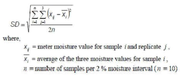
Repeatability requirements for SD are defined in column 4 of Part 1, Table 4(4)(i) for the appropriate 2 % moisture interval.
(iv) Reproducibility
Reproducibility between submitted instruments is estimated by calculating the standard deviation of differences, I SDD over the 6 % moisture range. The equation used to calculate instrument reproducibility is given below:
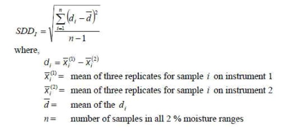
Reproducibility requirements are defined in column 5 of Part 1, Table 4(4) (i) for the 6 % moisture range.
(3) Basic instrument tests – influence factors
(i) Sample selections
Unless otherwise specified the following tests shall be performed using a single, stable moisture sample. Throughout the influence factor testing, portions of the grain samples shall be tested to determine that the moisture content is appropriate for the test and that the sample was stable throughout the test. As an example a reference moisture method or master instrument can be used. In any case, the method used to assess the sample stability shall be indicated in the test report.
(ii) Instrument stability
Three samples shall be tested, one from each of the three 2 % moisture interval samples of a single grain type (e.g. 10 % to 12 %, 12 % to 14 %, 14 % to 16 %). Number of repetitions: 5.
The minimum time period for assessing instrument stability shall be four weeks. Each of the 3 samples shall be measured 5 times through all of the meters submitted for type approval, prior to running any other type evaluation tests. The mean moisture content obtained for the 15 observations (3 samples × 5 replicates) shall be recorded. The 3 samples shall be stored and retested once all other type evaluation testing has been completed. The maximum permitted difference between the means of the two tests is defined in column 3 of Part 1, Table 4(4)(i)
(iii) Instrument warm-up time
Number of repetitions: 5.
The following test procedures shall be used to check warm-up times recommended by the manufacturer. If the manufacturer does not recommend a warm-up time, assume that turning the instrument power on will immediately provide accurate results.
Test sequence:
(1) Instrument powered off and stabilized at reference conditions (overnight).
(2) Instrument powered on, test after waiting for the specified warm-up time.
(3) Test after waiting one hour or twice the manufacturer’s recommended warm-up time, whichever is greater.
For an instrument where no warm-up time is specified, the sample shall be tested immediately upon the instrument being powered on and then again after 1 hour. The maximum permitted difference between the means of the two tests is defined in column 3 of Part 1, Table 4(4) (i).
(iv) Instrument power supply
(a) Main voltage variation
Number of repetitions: 10.
Voltage variation nominal voltage: (Unom) Unom – 15 %, Unom + 10 %
Voltage shall be varied to the above stated levels. Voltage settings shall be determined and recorded to ± 0.1 V. The difference between the mean moisture indication at the nominal voltage and the mean moisture indication at the tested extremes of voltage shall be evaluated.
The maximum permitted difference between the mean moisture meter value at nominal voltage and the mean value determined at the high and low voltage test points is defined in column 3 of Part 1, Table 4(4)(i).The maximum allowable standard deviation of 10 repeat measurements at any of the voltage levels is 0.10 %. For battery-powered devices the SD for 10 repeat measurements for a nominal battery charge is 0.10 %.
After each change in the voltage, the meter shall be allowed to stabilize for 30 minutes before testing.
(b) Low voltage of internal battery (not connected to the mains power)
The test method consists of a variation in the supply voltage. The objective of this test is to verify compliance with the provisions in Part 1, Table 4(4) (i) under conditions of low battery voltage.
The test procedure consists of exposure to the specified condition of the battery(s) for a period sufficient for achieving temperature stability and for performing the required measurements. If an alternative power source (standard power supply with sufficient current capacity) is used in bench testing to simulate the battery, it is important that the internal impedance of the specified type of battery also be simulated. The maximum internal impedance of the battery shall be specified by the manufacturer of the instrument.
Test sequence:
Stabilize the power supply at a voltage within the defined limits and apply the measurement and/or loading condition. Record the following data:
(a) Date and time
(b) Temperature
(c) Power supply voltage
(d) Functional mode
(e) Measurements and/or loading condition
(f) Indications (as applicable)
(g) Errors
(h) Functional performance
Reduce the power voltage to the EUT until the equipment clearly ceases to function properly according to the specifications and metrological requirements, and note the following data:
(i) Power supply voltage
(j) Indications
(k) Errors
(l) Other relevant responses of the instrument
The severity for this test is level 1. At level 1 the lower limit of the voltage is the lowest voltage at which the EUT functions properly according to the specifications and the number of cycles is at least one test cycle for each functional mode.
(v) Instrument storage temperature
Number of repetitions: 10.
The purpose of this test is to simulate extreme shipping conditions. The national responsible body may specify different temperature limits. A single sample is analyzed (n = 10) at reference conditions (Part 1, Table 4(1) (i)) prior to temperature cycling. The instrument is then powered down and placed in the environmental chamber. The chamber temperature is then increased to 50 °C or greater as specified by the national responsible body over a 1-hour period and maintained at that temperature for 3 hours. The chamber temperature is then decreased to –20 °C over a 1-hour period and maintained at that temperature for 3 hours. Repeat the temperature cycle. The instrument is equilibrated at reference conditions (Part 1, Table 4(1) (i)) for at least 12 hours unpowered. The instrument is turned on for the specified warm-up period and the test sample analyzed a second time (n = 10).
The mean of each replicate measurement shall be determined before and after temperature cycling. The maximum allowable difference in the mean values due to temperature cycling is defined in column 3 of Part 1, Table 4(4) (i).
(vi) Instrument levelling
(a) Instruments without level indicators
Number of repetitions: 5.
Reference tilt condition: instrument level within 0.1°
Degree of tilt: 5 % front to back and left to right (minimum of 2 orientations of tilt)
The test procedure consists of measuring the single sample with the instrument mounted on a level surface (reference alignment), then in each of the two orientations of tilt front-to-back and left to right, at a tilt of 5 %, returning to the reference alignment for the final test. Reference method portions shall be cut out from the bulk sample and submitted to the reference procedure or master meter before and after the instrument level tests and the results recorded.
The mean of each replicate measurement shall be determined for each orientation. The maximum allowable difference in the mean values of each tilt orientation from the mean of the two reference orientations is defined in column 3 of Part 1, Table 4(4) (i).
(b) Instruments with level indicators
Meters equipped with level indicators shall be tested at the indicated limits of the level indicator (front to back and left to right) rather than the specified tilt in 2(6) (i) Orientations similar to those in 2(6) (i) shall be applied with the same performance requirements.
(vii) Humidity
Number of repetitions: 10.
Instruments (power on) shall be placed in an environmental chamber at 22 °C and a relative humidity of 20 % for 16 hours. Samples shall be stored sealed at reference conditions. After equilibration the sample shall then be analyzed in the chamber. The relative humidity shall be raised to 90 % (22 °C) and, after the instrument has equilibrated at this humidity for at least 16 hours, the sample shall again be analyzed.
The mean of each replicate measurement shall be determined for each humidity level. The maximum allowable difference in the mean values between the two humidity levels is defined in column 3 of Part 1, Table 4(4) (i).
(viii) Instrument temperature sensitivity (converting to heat test and cold test)
One grain type
Three samples, one from each of the three 2 % moisture intervals of a single grain type (e.g. 10 % to 12 %, 12 % to 14 %, 14 % to 16 %)
Instruments shall be tested in an environment chamber at:
(1) Reference temperature, tR, 65 % RH.
(2) The lower operating temperature (t1), 65 % RH.
(3) The upper operating temperature (t2), constant humidity ratio of 0.005 kg
of water per kg of dry air. The manufacturer shall declare t1 and t2 as the instruments operating range. If the operating range is not declared then the minimum operating temperature range from 10 ºC to 30 ºC shall apply.
Instrument temperature sensitivity tests shall be run using three moisture level samples. Each sample shall be cut into 3 portions for testing at tR, at t1, and at t2. Instruments shall remain in the chamber throughout cycling to the appropriate temperatures; the sample shall be placed in the test chamber at the test temperature for at least 4 hours in a covered moisture inert container before instrument moisture measurements. Instruments shall be equilibrated to the new environmental conditions at least 4 hours prior to sample testing. The mean of each replicate measurement shall be determined for each temperature level. The maximum allowable difference in the mean values between tR, and t1 and tR, at t2 is 0.8 × the value in column 2 of Part 1, Table 4(4) (i).
Note: To facilitate testing of instrument temperature sensitivity, manufacturers shall provide a means of disabling the instrument feature for suppressing the display of moisture results when temperature ranges are exceeded. The national responsible body may address these requirements procedurally.
(4) Sample temperature sensitivity – influence factor test
Three grain types
Three 2 % moisture interval samples: (e.g. 10 % to 12 %, 12 % to 14 %, 14 % to 16 %)
Number of samples: (3 grain types, 3 moisture levels, duplicate samples at each moisture level)
Number of repetitions: 3
Instrument temperature: at reference conditions (Part 1, Table 4(1) (i)), reference temperature (tref)
Grain or seed temperatures: reference temperature (tref), manufacturer declared tref ± Δt or minimum Δt of ± 10 °C in case of no separate specification
Additional testing is required to verify that accurate results are provided when the sample and instrument are at different temperatures. This will be referred to as the sample temperature sensitivity test. The purpose of this test is to verify that the instrument provides accurate results when there is a difference in temperature between the sample and the instrument. The sample temperature sensitivity test shall be conducted using the three grain or seed types comprising three 2 % moisture intervals. For practical reasons due to the ability to accurately determine the reference value of elevated temperature grain samples, the maximum sample temperature for type approval testing shall be 45 °C.
The grain and seed test temperature shall be according to the manufacturer’s specification. If there is no separate specification, the minimum temperature difference requirement shall be ± 10 °C from the reference temperature. Tests shall be conducted with the instrument at reference temperature (tref , see Part 1, 4(1) (i)) and the sample temperature varying from tref – ΔtC to tref + ΔtH, where tref is the reference temperature. The manufacturer’s specified sample temperature for the sample above the instrument temperature is represented as tref + ΔtH and below as tref – ΔtC. The two temperature differences need not be equal. In no case shall tref + ΔtH be allowed to exceed 45 °C for the test.
Three moisture level analyses shall be made for each grain sample at each of the three test temperatures. The means for the 18 observations (2 samples × 3 moisture intervals × 3 replicates) of each grain or seed type shall be determined. The maximum permitted difference at the sample temperature extreme from moisture levels measured at reference sample temperature is 2.25 × column 3 of Part 1, Table 4(4) (i) for grain types in row I, otherwise it is 2 × column 3 of Part 1, Table 4(4) (i) for grain types in row II.
(5) Additional test for electronic instruments – disturbance tests (As per latest IS/ International Standards)
The disturbance tests in this section are described for a single instrument, i.e. one sample unit is the equipment under test (EUT). Testing with appropriate measures where the use of grain samples would not be possible or constructive due to the test conditions of the disturbance test is permitted.
(i) AC mains voltage dips, short interruptions and voltage variations
| Test method | Short-time reductions in mains voltage |
| Sample | One sample with mid-range moisture and stable moisture content. Allowable grains are specified by the national responsible body. Wheat is the preferred grain type.
Consecutive measurements per sample at each condition: 10 |
| Test procedure in brief | Over four tests, the EUT shall be subjected to voltage reductions and interruptions of varying intensity and duration.
A test generator suitable to reduce the amplitude of the AC mains voltage for a defined period of time is used. The performance of the test generator shall be verified before connecting to the EUT. The mains voltage interruptions and reductions shall be repeated with a time interval less than the time required for a single measurement so that at least one voltage interruption occurs per measurement. At least 10 cycles are necessary for each test to enable the required number of measurements. Record the following prior to and during each test: (a) moisture measurements; (b) indications and errors; and (c) functional performance. |
| Test severity | Test (a) Unom to zero for a duration equal to half a cycle of frequency
Test (b) Unom to zero for a duration equal to one cycle of frequency Test (c) Unom to 70 % reduction for a duration equal to 25/30* cycles of frequency Test (d) Unom to zero for a duration equal to 250/300* cycles of frequency |
| Notes | *Values are for 50 Hz and 60 Hz respectively |
| Requirements | All operational functions shall operate as designed (e.g. indicators).
The effect of the disturbance on moisture measurements shall not exceed a significant fault or the instrument shall detect and react to the fault (see Part 1, see Part 1, 2(27) and 2(38)) |
(ii) Bursts (transients) on AC mains
| Test method | Electrical bursts |
| Sample | One sample with mid-range moisture and stable moisture content. Allowable grains are specified by the national responsible body. Wheat is the preferred grain type.
Consecutive measurements per sample at each condition: 10 |
| Test procedure in brief |
The test consists of subjecting the EUT to bursts of double exponential wave form transient voltages. All bursts shall be applied during the same measurement in symmetrical mode and asymmetrical mode.
The characteristics of the burst generator shall be verified before connecting the EUT. The duration of the test shall not be less than 1 min for each amplitude and polarity. The injection network on the mains shall contain blocking filters to prevent the burst energy being dissipated in the mains. Record the following prior to test and during the application of bursts: (a) moisture measurements; (b) indications and errors; and (c) Functional performance. |
| Test severity | Amplitude (peak value): 1 kV
Repetition rate: 5 kHz |
| Number of test cycles | At least 10 positive and 10 negative randomly phased bursts shall be applied at 1000 V. The bursts are applied during all the time necessary to perform a measurement. At least 10 measurements shall be made with the bursts applied. |
| Requirements | All operational functions shall operate as designed (e.g. indicators).
The effect of the disturbance on moisture measurements shall not exceed a significant fault or the instrument shall detect and react to the fault (see Part 1, see Part 1, 2(27) and 2(38)) |
(iii) Radiated, radio-frequency, electromagnetic susceptibility
| Test method | Radiated electromagnetic field |
| Sample | One sample with mid-range moisture and stable moisture content. Allowable grains are specified by the national responsible body. Wheat is the preferred grain type.
One sample with mid-range moisture. |
| Test procedure in brief |
The test procedure involves the exposure of the EUT to electromagnetic field strength as specified by the severity level and field uniformity as defined by the referred standard.
The specified field strength shall be established prior to the actual testing (without the EUT in the field). The field shall be generated in two orthogonal polarizations and the frequency range shall be scanned slowly. If antennas with circular polarization (i.e. log-spiral or helical antennas) are used to generate the electromagnetic field, a change in the position of the antennas is not required. When the test is carried out in a shielded enclosure to comply with international laws prohibiting interference on radio The frequency ranges to be considered are swept with the modulated signal, pausing to adjust the RF signal level or to switch oscillators and antennas as necessary. Where the The dwell time of the amplitude modulated carrier at each frequency shall not be less than the time necessary for the EUT to be exercised and to respond, but shall in no case be less than 0.5 s. The sensitive frequencies (e.g. clock frequencies) shall be analyzed separately. Record the following prior to the test and then with radiated EM fields: (a) moisture measurements; (b) indications and errors; and (c) functional performance. |
| Test severity | EM frequency range: 26 MHz–2 GHz
For the frequency range 26–80 MHz, the testing laboratory may carry out the test according to 4(4) of this Part2 “Conducted RF fields”. Field strength: Radiated 10 V/m Modulation: 80 % AM, 1 kHz sine wave |
| Requirements | All operational functions shall operate as designed (e.g. indicators).
The effect of the disturbance on moisture measurements shall not exceed a significant fault or the instrument shall detect and react to the fault (see Part 1, 2(38) ) |
| Notes | The EM field can be generated in different facilities, however the use of which is limited by the dimensions of the EUT and the frequency range of the facility:
(a) the strip line is used at low frequencies (below 30 MHz or in some cases 150 MHz) for small EUT; (b) the long wire is used at low frequencies (below 30 MHz) for larger EUT; (c) dipole antennas or antennas with circular polarization placed at least 1 m from the EUT are used at high frequencies |
(iv) Conducted radio-frequency fields
| Test method | Conducted electromagnetic fields |
| Sample | One sample with mid-range moisture and stable moisture content.
Allowable grains are specified by the national responsible body. Wheat is the preferred grain type. Consecutive measurements per sample at each setting: as many as possible over the sweep across the frequency range. |
| Test procedure in brief | The test procedure involves the use of radio frequency EM current, simulating the influence of EM fields coupled or injected into the power ports and I/O ports of the EUT using coupling/decoupling devices as defined in the referred standard. The performance of the test equipment consisting of an RF generator, coupling devices, attenuators, etc. shall be verified. Record the following prior to the test and then with conducted EM fields:
(a) moisture measurements; (b) indications and errors; and (c) functional performance |
| Test severity | EM frequency range: 0.15–80* MHz
*For the frequency range 26–80 MHz, the testing laboratory may carry out the test according to 3(5)(iii) of Part-2. However, in case of dispute, the result from the test according to 3(5)(iv) of Part-2 shall prevail. RF amplitude (50 Ω): 10 V (e.m.f.) Modulation: 80 % AM, 1 kHz sine wave |
| Requirements | All operational functions shall operate as designed (e.g. indicators).
The effect of the disturbance on the moisture measurement shall not exceed a significant fault or the instrument shall detect and react to the fault (see Part 1, see Part 1, 2(27) and 2(38)) |
[File No. WM-9(8)/2024]
(Anupam Mishra)
Joint Secretary to the Government of India
Note:- The principal rules were published in the Gazette of India, Extraordinary, Part II, Section 3, Sub-section (i), vide notification number G.S.R.71(E), dated the 7th February, 2011 and was last amended, vide notification number G.S.R. 763 (E), dated the 4th October