Ministry of Consumer Affairs, Food & Public Distribution, Department of Consumer Affairs, has released draft rules under the Legal Metrology (General) Amendment Rules, 2024, for Automatic Level Gauges (ALGs) used in stationary storage tanks. These draft rules are available on the department’s website for stakeholder comments until February 6, 2025. Stakeholders, including State Legal Metrology Departments, industries, and associations, are invited to provide feedback via email to dirwm-ca@nic.in or mk.naik72@gov.in.
The draft rules introduce Part XIV in the Eighth Schedule of the Legal Metrology (General) Rules, 2011, detailing specifications for ALGs. These specifications include technical and metrological requirements, test procedures, and verification methods for ALGs in various tank types, such as vertical, cylindrical, pressurized, refrigerated, or heated tanks. The rules cover installation checks, error limits, and procedures for re-verification to ensure ALG accuracy. Practical challenges, especially for pressurized tanks, are also acknowledged.
Stakeholders are urged to review these provisions and provide comments to facilitate a comprehensive framework for ALG regulation. The finalized rules will come into effect upon their publication in the Official Gazette.
Government of India
Ministry of Consumer Affairs, Food & Public Distribution
Department of Consumer Affairs
Legal Metrology Division
Krishi Bhawan, New Delhi-01
Dated: 07.01.2025
Subject- Draft Rules for Automatic Level Gauges – comments from stakeholders – reg.
Undersigned is directed to refer to the above mentioned subject and to state that the Draft Rules for Automatic Level Gauges are placed in the website of the Department www.consumeraffairs.nic.in for seeking comments from all stakeholders by 06.02.2025. The comments may be sent to email-ID: dirwm-ca@nic.in / mk.naik72@gov.in .
(Ashutosh Agarwal)
Director (Legal Metrology)
Ph: 011-23389489
Email: dirwm-ca@nic.in
To:
All concerned (State Legal Metrology Departments, VCOs, Industries and Industry Associations)
[TO BE PUBLISHED IN THE GAZETTE OF INDIA, EXTRA ORDINARY, PART II SECTION 3 SUB-SECTION (i)]
GOVERNMENT OF INDIA
MINISTRY OF CONSUMER AFFAIRS, FOOD AND PUBLIC DISTRIBUTION
(DEPARTMENT OF CONSUMER AFFAIRS)
Notification
New Delhi, the …2025.
GSR……..(E).- In exercise of the powers conferred by sub-section (1) read with clauses (c), (f), (h), (i) and (s) of sub-section (1) of section 52 of the Legal Metrology Act 2009, (1 of 2010), the Central Government hereby makes the following rules, namely:-
1. Short title and commencement.-
(1) These rules shall be called the Legal Metrology (General) Amendment Rules, 2024.
(2) They shall come into force from the date of publication in the Official Gazette.
2. In the index of the Schedule of the Legal Metrology (General) Rules, 2011 under the Eight Schedule after Part XIII, the entries “Part XIV”, “Automatic Level Gauges for measuring the level of liquid in stationary storage tanks” shall be inserted.
3. In the Legal Metrology (General) Rules, 2011, (herein after referred to as the said rules), under the Eight Schedule the Part XIV and the entries made thereunder, the following shall be inserted, namely. –
EIGHTH SCHEDULE
SPECIFICATIONS FOR MEASURING INSTRUMENTS
PART XIV- AUTOMATIC LEVEL GAUGES FOR MEASURING THE LEVEL OF LIQUID IN
STATIONARY STORAGE TANKS
Part 1
1. Scope.
This Specification specifies the metrological and technical requirements and test procedures for automatic level gauges for storage tanks. Storage tanks include all the shapes for e.g. vertical and cylindrical storage tanks, and pressurized storage tanks (spheres, spheroid, bullets). The storage tanks may be refrigerated or heated. The metrological purpose of tank level measurements is the application in conjunction with tank calibration tables for the determination of liquid volume received from, delivered to, or contained in stationary storage tanks.
2. General definitions.- –
(1) Automatic level gauge (ALG), –
The instrument intended to measure automatically and display the level of the liquid contained in a tank with respect to a fixed reference. An automatic level gauge includes at least a liquid level sensor, a transducer, and an indicating device.
(2) Electronic automatic level gauge, –
Automatic level gauge using electronic means and/or equipped with electronic devices.
(3) Ancillary device, –
The device intended to perform a particular function, directly involved in elaborating, transmitting or displaying measurement results.
Examples:
(i) repeating indicating device;
(ii) printing device;
(iii) memory device, and
(iv) conversion
Note- For the purpose of this specification ancillary equipment, in so far as it is subject to metrological control, is considered to be part of the Automatic Level Gauge.
(4) Liquid level sensor, –
The element that senses the presence of the liquid surface and gives information on its level.
(5) Transducer, –
The device that provides an output quantity, having a determined relationship to the input quantity.
(6) Correction sensor, –
The sensor that measures a relevant property of the liquid and/or the medium above the liquid level for the purpose of applying a correction to the liquid level measurement.
(7) Calculator, –
The part of the ALG that receives the output signals from the transducer and, if applicable, from ancillary devices and/or other devices, processes them and, if appropriate, stores the results in memory until they are used. In addition, the calculator may be capable of communicating both ways with other devices.
(8) Indicating device, –
The part of the ALG that displays or prints the measuring result.
For the application of this specification the meaning of “indicating device” is broader than the general meaning in other specification (a printing device is considered as such).
(9) Repeating indicating device, –
The additional device (ancillary device) repeating the indication of the indicating device.
(10) Checking facility,-
The facility incorporated in an electronic automatic level gauge that enables:
(i) significant faults; and/or
(ii) incorrect functioning of a specific device of the Automatic Level Gauge; and/or
(iii) disturbed communication between specific devices of the Automatic Level Gauge to be detected and acted upon.
Note- “Acted upon” refers to any adequate response by the Automatic Level Gauge (luminous signal, acoustic signal, prevention of the measurement process, etc.).
(11) Automatic checking facility, –
The checking facility that operates without the intervention of an operator.
(12) Permanent automatic checking facility (type P), –
The automatic checking facility that operates at each measurement cycle.
(13) Intermittent automatic checking facility (type I), –
The automatic checking facility that operates at certain time intervals or per fixed number of measurement cycles.
(14) Dip plate, –
The horizontal plate located along the vertical axis descending from the upper reference point, providing a fixed contact surface from which manual liquid depth measurements are made.
The term “datum plate” is synonymous.
(15) Principal gauge hatch, –
The gauge hatch which has been designated for the principal measurements and is situated at a convenient, accessible and stable position.
(16) Dipping datum point, –
The intersection of the vertical measurement axis with the upper surface of the dip plate, or with the bottom surface of the tank if a dip plate is not provided. It constitutes the origin for the measurement of liquid levels (zero reference or dipping reference point).
(17) Upper reference point, –
The point clearly marked on the principal gauge hatch located along the vertical axis ascending from the dipping datum point to indicate the reference position to which ullage is measured.
(18) Gauge reference length, –
The distance between the dipping datum point and the zero point of the ALG.
(19) Dip, –
The vertical distance between the dipping datum point and the liquid level.
Note: The term “innage” is synonymous.
(20) Ullage, –
The distance between the liquid level and the upper reference point, measured along the vertical measurement axis.
Note: The term “outage” is synonymous.
(21) Rated operating conditions, –
The conditions of use, giving the range of values of influence quantities for which the metrological characteristics are intended to lie within the specified permissible errors.
Note: The rated operating conditions generally specify intervals of values for the quantity being measured and for any influence quantity.
(22) Reference conditions, –
The set of specified values of influence factors fixed to ensure valid intercomparisons of the results of measurements.
Note: Reference conditions generally specify intervals of values for any influence quantity.
(23) Influence quantity, –
The quantity which is not the subject of the measurement but which influences the value of the measurand
(24) Influence factor, –
The influence quantity having a value within the specified rated operating conditions of the ALG.
(25) Disturbance, –
The influence quantity having a value within specified limits, but outside the specified rated operating conditions of the ALG.
(26) Performance, –
The ability of the automatic level gauge to accomplish the intended functions.
(27) Durability, –
The ability of the automatic level gauge to maintain its performance characteristics over a period of use.
(28) Error (of indication), –
The indication of an automatic level gauge minus a true value of the corresponding input quantity.
(29) Maximum permissible error, –
The extreme permitted value by the present Specification for the error of indication.
(30) Intrinsic error, –
The error of an automatic level gauge determined under reference conditions.
(31) Initial intrinsic error, –
The intrinsic error of an automatic level gauge as determined prior to performance tests and durability evaluations.
(32) Fault, –
The difference between the error of indication and the intrinsic error of an automatic level gauge.
Note: Principally a fault is the result of an undesired change of data contained in or flowing through an Automatic Level Gauge.
(33) Significant fault, –
The fault greater than the maximum permissible error specified in Table 2. The following faults are considered not to be significant, even when they exceed the value defined above:
(i) The faults arising from simultaneous and mutually independent causes in the ALG itself or in its checking facilities;
(ii) the faults implying the impossibility to perform any measurement;
(iii) the transitory faults being momentary variations in the indication, which cannot be interpreted, memorized or transmitted as a measurement result;
(iv) faults giving rise to variations in the measurement results so serious that they are bound to be noticed by all those interested in the result of the measurement.
(34) Discrimination, –
The largest change in a stimulus that produces no detectable change in the response of a measuring instrument, the change in the stimulus taking place slowly and monotonically.
(35) Abbreviations, –
AC Alternating Current
ALG Automatic Level Gauge
AM Amplitude Modulation
ASD Acceleration Spectral Density
DC Direct Current
EM Electromagnetic
EMC Electromagnetic Compatibility
e.m.f. Electromotive force
ESD Electrostatic Discharge
EUT Equipment Under Test
GSM Global System for Mobile communication
IEC International Electrotechnical Commission
I/O Input / Output (refers to ports)
ISO International Organization for Standardization
MPE Maximum Permissible Error
N.A. Not Applicable
PC Personal Computer
RH Relative Humidity
RMS Root Mean Square
3. Description of the category of instrument. –
An automatic level gauge comprises at least a liquid-level sensor, a transducer, and an indicating device.
The general configuration of an automatic level gauge is given in Figure 1.
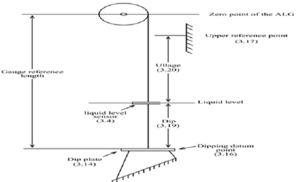
Figure 1 Some of the principal elements of an ALG, with reference to their definitions
The authorized units of measurement are those of the International System of Units (SI). Indications of the dip or, if applicable, the ullage shall be in standard units of length and shall be accompanied by the name or symbol of the unit. Indication of information that is not subject to metrological control is allowed, provided that it cannot be confused with metrological information.
Part II- Metrological and Technical Requirements
This part specifies the metrological and technical requirements and test procedures for ALGs for storage tanks. Storage tanks include all the shapes for e.g. vertical and cylindrical storage tanks, and pressurized storage tanks (spheres, spheroid, bullets). The storage tanks may be refrigerated or heated.
The metrological purpose of tank level measurements is the application in conjunction with tank calibration tables for the determination of liquid volume received from, delivered to, or contained in stationary storage tanks
2. Metrological requirements. –
(1) Rated operating conditions, –
The ALGs shall be designed and manufactured such that their errors do not exceed the maximum permissible error under the following rated operating conditions
Table-1 Rated operating conditions.
| (a) | Ambient temperature | low | + 5 °C, – 10 °C, – 25°C or – 40 °C(*) |
| high | +300C, +400C, +55°C or + 700C(*) | ||
| (b) | Relative humidity | Up to 93% | |
| (c) | DC mains voltage (*) | As specified by the manufacturer | |
| (d) | AC mains voltage (*) | Unom-15% to Unom +10% | |
| (e) | The minimum and maximum temperature of the liquid and the medium above the liquid |
As specified by the manufacturer |
|
| (f) | The minimum and maximum pressure in the tank | ||
| (g) | The characteristics of the liquid and of the medium above the liquid | ||
| (h) | The minimum and maximum densities of the liquid and of the medium above the liquid | ||
| * As per the expected conditions of application (indoor, outdoor, etc.) | |||
(2) Maximum permissible errors, –
(i) General, –
The maximum permissible error (MPE) of an ALG before installation is determined by testing under controlled conditions. The MPE of an ALG after installation is verified by comparing the ALG readings to the manual reference level measurement.
(ii) The maximum permissible errors, positive and negative, under rated operating conditions to be applied for the relevant indications are specified in Table 2.
Table-2 Maximum permissible error
| Description | Maximum permissible error (MPE) |
| (1) | (2) |
| Prior to installation | 1mm |
| After installation | 4mm |
The maximum permissible errors of Table 2 apply to the indication of a dip or an ullage according to the measuring principle of the ALG.
Note: The volume in the tank, calculated from the level measured and the tank calibration table, could be adversely affected by various factors. These factors include: tank bottom deformation, roof stability, and tank shell bulging that cannot be compensated.
(iii) The hysteresis error when changing the direction of the movement of the level shall not exceed 1 mm ( paragraph 5 of Annexure A of this part).
(iv) The MPE for the ALG “prior to installation” applies to the ALG itself, before being installed on the tank, for Model approval and for initial verification.
The MPE “after installation” applies to the ALG after installation on the storage tank, for initial verification and re-verification.
(v) The discrimination of the ALG itself shall be such that level measurements are in all cases within 1 mm.
(3) Presumption of compliance
An ALG is presumed to comply with the provisions in sub-paragraph (1) of paragraph 2 and sub-paragraph (2) of paragraph 2 of this part if it passes the relevant tests specified under this specification.
(1) Indicating device, –
(i) For an analog indication, the distance between successive marks on the scale shall be not less than 1 mm.
(ii) An indicating device can be either a local indicating device which is a part of the body or located in the immediate vicinity of the level gauge, respectively, or a repeating indicating device located at a distance more or less far away from the level gauge. A repeating indicating device is often used for observation of the ALG indication in an easily accessible location (such as a control room).
If there are more than one indicating devices, each of them shall comply with the maximum permissible error specified in clause (ii) of sub-paragraph (2) of paragraph 2 of this part. The difference between any two indicating devices shall not be greater than 1 mm (or the digital scale equivalent) under stable level conditions.
The local indicating device or the repeating indicating device shall sound an alarm when the operational limits of the level gauge are reached (maximum and minimum heights).
Indicating devices that are not subject to legal metrological control may be connected, but it must be clearly marked that they are not subject to legal control and they must not have an interaction with the electronics of the ALG.
(iii) An additional indicating device may be common when connected to more than one
(iv) A remote indication on an indicating device shall be unambiguously identified with respect to the ALG it belongs to.
(v) An ALG shall indicate the innage (dip). Other measured values, such as ullage, may be indicated on the same display but these indications shall be replaced by the innage within 10 For metrological purposes, an indication of the ullage shall either be permanently available or be available on demand, together with the indication that the ullage is presented and, if applicable, which ALG is presented.
(vi) Reading of the results shall be reliable, easy and unambiguous under conditions of normal use. The figures forming the results shall be of a size, shape and clarity for reading to be The scales, numbering and printing shall permit the figures which form the results to be read by simple juxtaposition.
(vii) The presentation of the measurement results shall contain the names or symbols of the units of length in which they are expressed.
The scale interval of each display or print must be in the form 1 × 10 n, 2 × 10 n, or 5 ×10n units of length, n being a whole positive or negative number, or zero.
(viii) A digital indication shall display at least one figure beginning at the extreme A decimal fraction shall be separated from its integer by a decimal sign (in general a comma or in English speaking countries a dot on the line), with the indication showing at least one figure to the left of the sign and all figures to the right. Zero may be indicated by one zero to the extreme right, without a decimal sign. The unit shall be chosen so that the displayed or printed values have not more than one non- significant zero to the right. For values with decimal sign, the non-significant zero is allowed only in the third position after the decimal sign.
(ix) The clause (ii) of sub-paragraph (1) of paragraph 3 through clause (viii) of sub-paragraph (1) of paragraph 3 of this part are also applicable to printing devices, as
(2) Additional technical requirements for ALGs with movable sensor, –
(i) Suspension mechanism, –
In order to facilitate checks on the mechanism of the gauge, where applicable, the ALG shall be provided with means allowing to impart on request a movement to the working parts of the gauge.
Note: An example of a situation where this is applicable, is a dipstick having a movable part (the float) but the gauge does not have the possibility to force a movement.
(ii) Static position, –
If the level sensor can be statically positioned above or below the liquid level, it shall be made unambiguously clear that the indication is not presenting an actual measurement.
(3) Installation requirements, –
(i) General, –
(a) ALGs shall be installed in such a way that the requirements of sub-paragraph (3) of paragraph 3 through sub-paragraph (7) of paragraph 3 of this part are The indication shall be easily accessible and legible.
(b) For metrological purposes, ALGs shall be equipped and installed in such a way that they can be verified when mounted on the tank and with the tank in service.
(c) The liquid level sensor shall be in close proximity to the official gauge hatch if The ALG shall be installed in such a way that the operation of the liquid level sensor, or the measurement by the ALG, shall not be obstructed by obstacles.
(d) If the procedure during verification, sampling, affects the ALG measurement such that a significant fault occurs, this shall be clearly indicated.
(e) The ALG shall be installed in such a way that the influence of eddies, currents, turbulence, foam, condensation, variation of process conditions, asymmetrical heating, wind and other effects have a negligible effect on the performance of the ALG.
If applicable, adequate protection shall be provided.
(f) The ALG shall be installed on the tank in such a way that the deviation of the gauge reference length plus level due to movement of the tank shell, tank bottom, tank roof or stilling well remains within the MPE after installation (4 mm).
(g) If provided, the correction sensor shall be situated in such a way that a reliable value of the properties intended to be measured is If necessary, more than one sensor shall be installed in order to obtain a correct average value.
(h) The thermal expansion of the tank shell or, if applicable, the support pipe, shall be such that the total deviation for temperature changes will fall within the maximum permissible errors for the installed ALG, or if necessary compensated for.
Note-This requirement may be verified by calculation.
(4) Ancillary devices, –
The ancillary devices shall not affect the measurement and shall have no characteristics that facilitate fraudulent use.
(5) Markings, –
(i) ALGs shall be legibly and clearly marked with the following information:
(a) name of the manufacturer or trademark;
(b) type designation;
(c) serial number and year of manufacture;
(d) Model approval number, and
(e) any other specific information if any.
(ii) The repeating indicating device(s) shall be marked with the following information:
(a) Model approval number;
(b) identifications of the
(iii) The descriptive markings shall be indelible and of a size, shape and clarity allowing easy reading under operating conditions of the They shall be grouped together in a clearly visible place on the ALG itself or on a data plate fixed to it.
(6) Verification marks, –
ALGs shall have a place for the verification marks which is visible and which allows easy application of the marks. It shall be impossible to remove the marks without damaging them.
(7) Sealing, –
It shall be possible to seal the data plate mentioned in clause (iii) of sub-paragraph (5) of paragraph 3 of this part bearing the markings, unless this plate cannot be removed without being destroyed.
Sealing means shall be provided for those parts that can affect the accuracy of the measurement and which are not intended to be accessible by the user. Sealing may be carried out with metal, plastic or other suitable material as long as it is sufficiently durable and provides evidence of tampering.
When access to parameters that participate in the determination of results of measurements is not protected by mechanical sealing devices, an electronic sealing can be applied. The software sealing shall fulfill the following provisions:
(i) access shall only be allowed to legal metrology officer, g. by using a “password” and, after changing parameters, the ALG may be put into use “in sealed condition” again without any restriction;
or access is allowed without restrictions (similar to classical sealing) but, after changing parameters, the ALG shall only be put into use “in sealed condition” again by authorized legal metrology officer, e.g. by using a “password”;
(ii) the “password” must be changeable;
(iii) the device shall either clearly indicate when it is in the configuration mode (not under legal metrological control), or it shall not operate while in this This status shall remain until the ALG has been put into use “in sealed condition”;
(iv) for identification, data concerning the latest intervention shall be recorded in an event logger. The record shall include at least:
(a) an event counter;
(b) the date the parameter was changed;
(c) the new value of the parameter; and
(d) an identification of the person that implemented the
(v) the traceability of the last intervention shall be assured for at least two years, if it is not over-written on the occasion of a further intervention If it is possible to store more than one intervention, and if deletion of a previous intervention must occur to permit a new record, the oldest record shall be deleted.
(8) Safeguarding the integrity of the measurement, –
(i) General requirements, –
ALGs shall be designed and manufactured such that their metrological functions are safeguarded and their errors do not exceed the limits of the maximum permissible errors under rated operating
conditions. It shall be possible to determine the presence and correct functioning of the checking facilities. The checking facilities shall be of type I or P.
(ii)Prevention or signaling of significant faults, –
(a) ALGs shall be designed and manufactured such that when they are exposed to the following disturbances, either:
(I) significant faults do not occur; or
(II) significant faults are detected and acted upon by means of a checking facility during the following disturbances:
(A) radiated, radio-frequency, electromagnetic fields;
(B) conducted radio-frequency fields;
(C) electrostatic discharge;
(D) bursts (transients) on signal, data and control lines;
(E) surges on signal, data and control lines;
(F) AC mains voltage dips, short interruptions and voltage variations;
(G) bursts (transients) on AC and DC mains;
(H) voltage dips, short interruptions and voltage variations on DC mains power;
(I) ripple on DC mains
(III) significant faults are detected and acted upon by means of a checking facility after the following disturbances:
(A) damp heat cyclic (condensing);
(B) surges on AC and DC mains
Note: A fault equal to or smaller than the significant fault according to sub-paragraph (32) of paragraph 1 of part-I is allowed irrespective of the value of the error of indication.
(b) The provisions in item (I) of sub-clause (a) of clause (ii) of sub-paragraph (8) of paragraph 3 and item (II) of sub-clause (a) of clause (ii) of sub-paragraph (8) of paragraph 3of this part may be applied separately to:
(i)each individual cause of significant fault; and/or
(ii)each part of the ALG.
Note: In case of a disturbance, a fault equal to or smaller than the MPE as specified in Table 1 is allowed, irrespective of the value of the error of indication.
(C) The provisions in clause (i) of sub-paragraph (8) of paragraph 3 and clause (ii) of sub-paragraph (8) of paragraph 3 of this part shall be met ALGs shall be designed and manufactured such that either:
(i)significant durability errors do not occur; or
(ii)significant durability errors are detected and acted upon by means of a durability protection facility.
(4) The choice of whether item (I) or item (II) of sub-clause (a) of clause (ii) of sub-paragraph (8) of paragraph 3 and whether item (I) or (III) of sub-clause (a) of clause (ii) of sub-paragraph (8) of paragraph 3 of this part is applied, is left to the manufacturer.
(5) If a significant fault is detected by a checking facility, a visual and/or audible indication shall automatically occur and shall continue until the user takes action or the fault is
(6) The type of an ALG is presumed to comply with the provisions in sub-clause (a) of clause (ii) of sub-paragraph (8) of paragraph 3 of this part if it passes the relevant examination and tests specified under this specification.
(iii) Signaling the loss or distortion of data
(a) The loss or distortion of data shall be signaled by one or more checking facilities enabling:
(I) incorrect functioning of a specific device of the ALG; and
(II) disturbed communication between specific devices of the ALG to be detected and acted
If a risk of loss or distortion of data is detected by a checking facility, a visual and/or audible indication shall automatically occur and shall continue until the user takes action or the fault is corrected.
(b) The design of the ALG shall ensure that permanently memorized instructions and data are correct ).
(c) All relevant measurement data shall be checked for correct value whenever they are transferred or stored internally or transmitted to peripheral equipment by interface, by such means as:
(I) parity bit;
(II) check sum;
(III) independent double storage; or
(IV) other handshake-routine with
(d) Checking facilities of the calculator
The objective of checking the functioning of the calculator is to verify that the values of all permanently memorized instructions and data are correct, and all procedures of internal transfer and storage of data relevant to the measurement result are performed correctly.
The objective is to check the correct value of all data related to the measurement whenever these data are internally stored or transmitted to an ancillary device through an interface. In addition, the calculation system shall be provided with a means of controlling the continuity of the calculation program (“watch-dog”).
(e) Checking facilities of the indicating device
The instrument shall automatically check the data transmitted to the indicating device and the electronic circuits used for the indicating device, except the driving circuits of the display itself. The display may be checked either automatically or manually.
If the failure of an indicator display element can cause a false indication then the instrument shall have a display test facility which on demand will show all relevant signs of the indicator display in their active and non-active states for a sufficient time to be easily observed by the operator.
If a PC is used as a common indication device, and the communication with the transducer is digital, it is assumed that the device meets the requirements for the checking facilities.
(f) Checking facilities of ancillary devices
Devices intended to perform a particular function, involved in elaborating and transmitting measurement results for custody transfer purposes, shall be checked for presence and correct operation.
Devices intended to perform a particular function, involved in transmitting or displaying measurement results for custody transfer purposes, shall also comply with 3(8)(iii).
The object of this checking facility is to verify the presence of the ancillary device, and to verify the correct transmission of data from the calculator to the ancillary device.
Note: The use of parity bit alone is not sufficient in case of storing or reading metrological data for an electronic ALG.
4. Metrological controls and Tests
Metrological control of instrument shall consists of the following- Model approval, verification and re- verification.
(1)Model Approval
(i) Number of units submitted to type test
The applicant for the type test shall supply at least one production sample of the instrument for type testing.
In case the applicant wants to have several versions or measuring ranges approved, the central government decides which version(s) and range(s) shall be supplied.
Several tests can be carried out in parallel on different specimens. In this case, central government decides which version or measuring range shall be subjected to a specific test.
If a specimen does not pass a specific test and as a result has to be modified or repaired, the applicant shall carry out this modification to all the instruments supplied for test. If the testing laboratory has sound reasons to fear that the modification has a negative influence on tests that already had a positive result, these tests shall be repeated.
(ii) Documentation
The documentation submitted with the application for type approval shall include:
(a) a list of the electronic sub-assemblies with their essential characteristics;
(b) a description of the electronic devices with drawings, diagrams and general software information explaining their characteristics and operation;
(c) mechanical drawings;
(d) installation and security sealing plan;
(e) operating instructions;
(f) test outputs, their use, and their relationships to the parameters being measured; and
(g) documentation or other evidence that supports the assumption that the design and characteristics of the measuring instrument comply with the requirements of this
(iii) Equipment under test (EUT)
As a rule, tests will be carried out on the complete ALG.
Simulation of any part of the ALG tested should be avoided. If this is not possible, all parts of the ALG that can be affected by the influence factor or disturbance shall play an active role in the measurements.
If the size or configuration of the ALG does not lend itself to testing as a whole unit, or if only a separate device of the measuring instrument is concerned, the tests, or certain tests, shall be carried out on the devices (modules) separately, provided that, in case of tests with the devices in operation, these devices are included in a simulated setup, sufficiently representative of its normal operation.
Note: As a general rule, the dismantling of the ALG or devices for the tests is not intended.
(2) Tests for Type evaluation
(i) General
Tests shall be carried out on the complete ALG.
Simulation of any part of the ALG tested should be avoided. If this is not possible, all parts of the ALG that can be affected by the influence factor or disturbance shall play an active role in the measurements.
If the size or configuration of the ALG does not lend itself to testing as a whole unit, or if only a separate device of the measuring instrument is concerned, the tests, or certain tests, shall be carried out on the devices (modules) separately, provided that, in case of tests with the devices in operation, these devices are included in a simulated setup, sufficiently representative of its normal operation.
Note: The dismantling of the ALG or devices for the tests is not intended.
(ii) Reference conditions
Except for the parameter being tested, the following reference conditions shall be kept by the testing laboratory during the tests:
| Sl.no | Influence | Value |
| (a) | Temperature | 20 °C ± 5 °C |
| (b) | Relative humidity | < 85 % |
| (c) | DC mains voltage (*) | Les than 10 % of the variation specified by the manufacturer of the EUT |
| (d) | AC mains voltage (*) | Unom ± 1 % |
| (e) | AC mains frequency (*) | fnom ± 0.5 % |
| (*) whatever is applicable | ||
Tests are carried out under atmospheric pressure
(iii)Tests prior to installation of the ALG on the tank.
The procedures described in sub-paragraph (1) of paragraph 5 of this part pertain to the tests to be carried out prior to installation of the ALG on the tank.
The equipment under test shall be clean and free of moisture. It shall be mounted and put into operation in accordance with the manufacturer’s specifications before the test is started. The EUT shall be in normal operation throughout the test. The EUT shall be thoroughly checked after the termination of each test and sufficient time shall be allowed for recovery.
Tests shall be performed under normal test conditions. When the effect of one influence factor or disturbance is being evaluated, all other factors have to be held relatively constant, at values within the reference conditions defined in clause (ii) of sub-paragraph (2) of paragraph 5 of this part. The electromagnetic environment of the laboratory shall not influence the test results.
The temperature is considered to be constant when the difference between the extreme temperatures noted during the test does not exceed 5 °C, and the rate of change does not exceed 5 °C per hour.
When subjected to the effect of influence factors as provided for in sub-paragraph (6) of paragraph 5 of this part the instrument shall continue to operate correctly and the indications shall be within the maximum permissible errors.
(3) Accuracy Test
Consecutive levels rising from zero to a value close to the measuring range and similarly descending shall (as far as possible) be equally distributed over the measuring range.
The number of levels shall be at least as follows:
(i) when determining the initial intrinsic error: at least 10 levels; For other determinations:
(ii) influence tests: at least 3 levels;
(iii) disturbance tests: at least 1 level (at about 50 % of the measuring range).
(4) Discrimination Test
ALGs without a movable liquid level detecting element are presumed to comply with the provisions in clause (v) of sub-paragraph (2) of paragraph 2 without being subjected to this test. This justification shall be mentioned in the test report.
To test compliance with clause (v) of sub-paragraph (2) of paragraph 2 of this part, constitute three different levels, (as far as possible) equally distributed over the measuring range, rising and descending. From a stable position, the level shall be changed in the same direction with the value of clause (v) of sub-paragraph (2) of paragraph 2 of this part (1 mm). The change of the indication is noted.
(5) Hysteresis Test
ALGs without a movable liquid level detecting element are presumed to comply with the provisions in clause (iii) of sub-paragraph (2) of paragraph 2, without being subjected to this test. This justification shall be mentioned in the test report.
To test compliance with clause (iii) of sub-paragraph (2) of paragraph 2 of this part, this test shall be performed at three different levels, equally distributed between the first point of verification and the limit of the measuring range, upper or lower height according to the movement of the ALG.
Starting from the first point of verification, raise the level over a distance of about 1/3 of the measuring range, allow stabilization and read the indication. Then change the level about 1/10 of the measuring range and after that change the level until the first stabilized level is reached. Again allow stabilization and read the indication. Carry out this sequence two more times, now starting from the previous stabilized level.
Repeat these measurements starting from a value close to the measuring range and proceed inverting the direction of the movements. Evaluate the error.
Note: If the instrument has more than one indicating device, the indications of the various devices shall be compared during the performance tests and shall comply with clause (ii) of sub-paragraph (1) of paragraph 3 of this part.
(6) Influence factor tests
The type of an ALG is presumed to comply with the provisions specified in sub-paragraph (1) of paragraph 2 of this part if it passes the tests in clause (i) of sub-paragraph (6) of paragraph 5 to clause (iv) of sub-paragraph (6) of paragraph 5 of this part.
(i) Maximum permissible error under reference conditions
Before, during, and after the tests clause (ii) of sub-paragraph (6) of paragraph 5 to clause (iv) of sub-paragraph (6) of paragraph 5 of this part, all functions shall operate as designed and the error of the ALG shall not exceed the limits of the maximum permissible error “before installation” specified in sub-paragraph (2) of paragraph 2 of this part under the reference conditions in clause (ii) of sub-paragraph (2) of paragraph 5 of this part.
(ii) Static temperatures
(a) Dry heat (non condensing)
This test is applied to verify compliance with the provisions in clause (i) of sub-paragraph (1) of paragraph 2of this part under condition of dry heat (high environmental temperature).
| (a) |
Test procedure in brief: |
The test consists of exposure to the specified high temperature under “free air” conditions for the time specified (the time specified is the time after the EUT has reached temperature stability).
The change of temperature shall not exceed 1 °C/min during heating up and cooling down. The absolute humidity of the test atmosphere shall not exceed 20 g/m3. When testing is performed at temperatures lower than 35 °C, the relative humidity shall not exceed 50 %. After stabilization at the relevant temperature, the following tests shall be carried out: (i) an accuracy test at three different levels equally spaced in the measuring range; (ii) a discrimination test at one level; (iii) an hysteresis test at one level. |
|||||
| (b) | Test severities: | The following severities may be specified | |||||
| (c) | Severity level: | 1 | 2 | 3 | 4 | Unit | |
| (d) | Temperature: | 30 | 40 | 55 | 70 | °C | |
| (e) | Duration: | 2 | 2 | 2 | 2 | h | |
| (f) | Condition of the EUT: | Normal power supplied and “on” for a time period equal to or greater than the warm-up time specified by the manufacturer.
Power is to be “on” for the duration of the test. |
|||||
| (g) | Stabilization: | 2 hours at each temperature under “free air” conditions. | |||||
| (h) | Requirement: | All functions shall operate as designed. All errors shall be within the maximum permissible errors specified in sub-paragraph (2) of paragraph 2 | |||||
| (i) | Note: | The applicable severity level depends on the climatic conditions and the expected conditions of application (indoors, outdoors, etc.). | |||||
Page Contents
(b) Cold
This test is applied to verify compliance with the provisions in clause (i) of sub-paragraph (1) of paragraph 2 of this part under condition of cold (low environmental temperature).
| (a) | Test procedure in brief: | The test consists of exposure to the specified low temperature under “free air” conditions for the time specified (the time specified is the time after the EUT has reached temperature stability). | |||||
| The change of temperature shall not exceed 1 °C/min during heating up and cooling down. | |||||||
| IEC specifies that the power to the EUT shall be switched off before the temperature is raised. | |||||||
| After stabilization at the relevant temperature, the following tests shall be carried out: | |||||||
| (i) an accuracy test at three different levels equally spaced in the
measuring range; (ii) a discrimination test at one level; |
|||||||
| (iii) an hysteresis test at one level. | |||||||
| (b) | Test severities: | The following severities may be specified | |||||
| (c) | Severity level: | 1 | 2 | 3 | 4 | Unit | |
| (d) | Temperature: | +5 | –10 | –25 | –40 | °C | |
| (e) | Duration: | 2 | 2 | 2 | 2 | h | |
| (f) | Condition of the EUT: | Normal power supplied and “on” for a time period equal to or greater than the warm-up time specified by the manufacturer. Power is to be “on” for the duration of the test. | |||||
| (g) | Stabilization: | 2 hours at each temperature under “free air” conditions. | |||||
| (h) | Requirement: | All functions shall operate as designed. All errors shall be within the maximum permissible errors specified in sub-paragraph (2) of paragraph 2. | |||||
| (i) | Note: | The applicable severity level depends on the climatic conditions and the expected conditions of application (indoors, outdoors, etc.). | |||||
(iii) DC mains voltage variation
This test is only applicable for ALGs powered by DC networks and is applied to verify compliance with the provisions in clause(c) of sub-paragraph (1) of paragraph 2 of this part under condition of DC mains voltage variation. In case this test is not applicable, the justification shall be mentioned in the test report.
| (a) |
Test procedure in brief: |
The test consists of exposure to the specified power supply condition for a period sufficient for establishing stability.
For both the upper and the lower limit of DC level, an accuracy test at three different levels equally spaced in the measuring range shall be carried out. |
| (b) |
Test severity: |
The upper limit will be the DC level at which the EUT has been manufactured to automatically detect high-level conditions.
The lower limit will be the DC level at which the EUT has been manufactured to automatically detect low-level conditions. |
| (c) | Requirement: | The EUT shall comply with the specified maximum permissible errors. This applies at all voltage levels between the two levels. |
(iv) AC mains voltage variation
This test is only applicable for ALGs powered by public AC networks and is applied to verify compliance with the provisions in clause(d) of sub-paragraph (1) of paragraph 2 of this part under condition of AC mains voltage variation. In case this test is not applicable, the justification shall be mentioned in the test report.
| (a) | Test procedure in brief: | The test consists of exposure to the specified power condition for a period sufficient for achieving temperature stability and for performing the required measurements.
For both the upper and the lower limit of AC level, an accuracy test at three different levels equally spaced in the measuring range shall be carried out. |
|
| (b) | Mains voltage : | Upper limit | Unom + 10 % |
| (c) | Lower limit | Unom – 15 % | |
| (d) | Notes: | In the case of three-phase mains power, the voltage variation shall apply for
each phase successively. The values of Unom are those marked on the measuring instrument. In case a range is specified, the “–” relates to the lowest value and the “+” to the highest value of the range. |
|
| (e) | Requirement: | The EUT shall comply with the specified maximum permissible errors. This applies at all voltage levels between the two levels. | |
(7) Disturbances
The type of ALG is presumed to comply with the provisions specified in sub-clause (a) of clause (ii) of sub-paragraph (8) of paragraph 3 of this part, if it passes the following tests:
(i) Damp heat, cyclic (condensing)
This test is applied to verify compliance with the provisions in sub-item(a) of item (III) of sub-clause (a) of clause (ii) of sub-paragraph (8) of paragraph 3 of this part after condition of condensing humidity, combined with cyclic temperature changes.
| (a) | Test procedure in brief: | The test consists of exposure to cyclic temperature variation between 25 °C and a temperature of + 55 °C, maintaining the relative humidity above 95 % during the temperature change and low temperature phases, and at 93 % at the upper temperature phases.
Condensation should occur on the EUT during the temperature rise. The 24 h cycle consists of: (1) temperature rise during 3 h; (2) temperature maintained at upper value until 12 h from the start of the cycle; (3) temperature lowered to lower value within 3 h to 6 h, the rate of fall during the first hour and a half being such that the lower value would be reached in 3 h; (4) temperature maintained at lower value until the 24 h cycle is completed; (5) immediately after the 24 h cycle, the ALG shall be switched on and an accuracy test shall be carried out for at least one level at about 50 % of the measuring range. The stabilizing period before and recovery after the cyclic exposure shall be such that all parts of the EUT are within 3 °C of their final temperature. During the disturbance, the ALG shall be switched off. |
|
| (b) | Severity level: | 2 | unit |
| (c) | Upper temperature: | 55 | °C |
| (d) | Duration: | 2 | cycles |
| (e) | Requirement: | During the disturbance, either:
(a) Significant faults do not occur; or Significant faults are detected and acted upon by means of a checking facility. |
|
Note: This test shall not be confused with the temperature test.
(ii)Electromagnetic susceptibility
(a) Radiated, radio-frequency, electromagnetic fields
For instruments containing electronics, this test is applied to verify compliance with the provisions in sub-item (A) of item (II) of sub-clause (a) of clause (ii) of sub-paragraph (8) of paragraph 3 under conditions of radiated electromagnetic fields.
Instruments that do not contain any active electronic circuits (transistors, ICs, radio tubes), are presumed to comply with the provisions in sub-clause (a) of clause (ii) of sub-paragraph (8) of paragraph 3 of this part, without being subjected to this test.
In case this test is not applicable, the justification shall be mentioned in the test report.
| (a) |
Test procedure in brief: |
The EUT shall be exposed to electromagnetic field strength as specified by the severity level (10 V/m) and a field uniformity as defined by the referred standard.
The frequency ranges to be considered are swept with the modulated signal, pausing to adjust the RF signal level or to switch oscillators and antennas as necessary. Where the frequency range is swept incrementally, the step size shall not exceed 1 % of the preceding frequency value. The dwell time of the amplitude modulated carrier at each frequency shall not be less than the time necessary for the EUT to be exercised and to respond, but shall in no case be less than 0.5 s. The sensitive frequencies (e.g. clock frequencies) shall be analyzed separately. During the disturbance, an accuracy test shall be carried out for at least one level at about 50 % of the measuring range. |
| (b) | Severity level: | 3 |
| (c) | Field strength: | 10 V/m |
| (d) | Frequency range:
|
80 MHz – 2 GHz , 26 MHz – 2 GHz |
| (e) | Modulation: | 80 % AM, 1 kHz, sine wave |
| (f) | Requirement
: |
During the disturbance, either:
(a) Significant faults do not occur; or (b) Significant faults are detected and acted upon by means of a checking facility. |
| (g) | Notes: | Usually, these sensitive frequencies can be expected to be the frequencies emitted by the EUT.
|
(b) Conducted, radio-frequency, electromagnetic fields
For instruments containing electronics, this test is applied to verify compliance with the provisions in sub-item (B) of item (II) of sub-clause (a) of clause (ii) of sub-paragraph (8) of paragraph 3 under conditions of conducted electromagnetic fields.
Instruments that do not contain any active electronic circuits (transistors, ICs, radio tubes) and/or mains or other input or output port, are presumed to comply with the provisions in sub-item (B) of item (II) of sub-clause (a) of clause (ii) of sub-paragraph (8) of paragraph 3 of this part, without being subjected to this test.
In case this test is not applicable, the justification shall be mentioned in the test report.
| (a) | Test procedure in brief: | Radio frequency EM current, simulating the influence of EM fields shall be coupled or injected into the power ports and I/O ports of the EUT using coupling/decoupling devices as defined in the referred standard.
During the disturbance, an accuracy test shall be carried out for at least one level at about 50 % of the measuring range. |
|
| (b) | Severity level: | 3 | unit |
| (c) | RF amplitude (50 Ω ): | 10 | V (e.m.f.) |
| (d) | Frequency range: | 0.15 – 80 | MHz |
| (e) | Modulation: | 80 % AM, 1 kHz sine wave | |
| (f) | Notes: | If the EUT is composed of several elements, the tests shall be performed at each extremity of the cable if both of the elements are part of the EUT.
For the frequency range 26 – 80 MHz, the testing laboratory can either carry out the test according to sub-clause (a) of clause (ii) of sub-paragraph (7) of paragraph 5 or according to sub-clause (b) of clause (ii) of sub-paragraph (7) of paragraph 5 of this part. But in case of a dispute, the results according to sub-clause (b) of clause (ii) of sub-paragraph (7) of paragraph 5 of this part shall prevail. |
|
| (g) | Requirement: | During the disturbance, either:
(b) Significant faults do not occur; or (c) Significant faults are detected and acted upon by means of a checking facility. |
|
(c) Electrostatic discharge
For instruments containing electronics, this test is applied to verify compliance with the provisions in sub-item (C) of item (II) of sub-clause (a) of clause (ii) of sub-paragraph (8) of paragraph 3 under conditions of electrostatic discharges.
Instruments that do not contain any active electronic circuits (transistors, ICs, radio tubes), are presumed to comply with the provisions in sub-item (C) of item (II) of sub-clause (a) of clause (ii) of sub-paragraph (8) of paragraph 3 of this part, without being subjected to this test. In case this test is not applicable, the justification shall be mentioned in the test report.
| (a) | Test procedure in brief: | An ESD generator shall be used with a performance.
At least 10 discharges shall be applied. The time interval between successive discharges shall be at least 10 seconds. For EUT not equipped with a ground terminal, the EUT shall be fully discharged between discharges. Contact discharge is the preferred test method. Air discharge shall be used where contact discharge cannot be applied. Direct application: In the contact discharge mode to be carried out on conductive surfaces, the electrode shall be in contact with the EUT. In the air discharge mode on insulated surfaces, the electrode is approached to the EUT and the discharge occurs by spark. Indirect application: The discharges are applied in the contact mode to coupling planes mounted in the vicinity of the EUT. During the disturbance, an accuracy test shall be carried out for at least one level at about 50 % of the measuring range. |
||
| (b) | Severity level: | 3 | unit | |
| (c) | Test voltage: | Contact discharge | 6 | kV |
| Air discharge | 8 | kV | ||
| (d) | Notes: | Contact discharges shall be applied on conductive surfaces. Air discharges shall be applied on non-conductive surfaces. | ||
| (e) | Requirement: | During the disturbance, either:
(a) Significant faults do not occur; or (b) Significant faults are detected and acted upon by means of a checking facility. |
||
(d) Bursts (transients) on signal, data and control lines
For instruments containing electronics and provided with I/O or communication ports, this test is applied to verify compliance with the provisions in sub-item (D) of item (II) of sub-clause (a) of clause (ii) of sub-paragraph (8) of paragraph 3 of this part under conditions where electrical bursts are superimposed on I/O and communication ports.
Instruments that do not contain any active electronic circuits (transistors, ICs, radio tubes), or not being provided with external signal, data or control lines, are presumed to comply with the provisions in sub-item (D) of item (II) of sub-clause (a) of clause (ii) of sub-paragraph (8) of paragraph 3 of this part ,without being subjected to this test.
In case this test is not applicable, the justification shall be mentioned in the test report.
| (a) | Test procedure in brief: | A burst generator shall be used with the performance characteristics as specified in the referred standard.
The test consists of exposure to bursts of voltage spikes for which the output voltage on 50 Ω and 1 000 Ω load are defined in the referred standard. Both positive and negative polarity of the bursts shall be applied. The duration of the test shall not be less than 1 min for each amplitude and polarity. For the coupling of the bursts into the I/O and communication lines, a capacitive coupling clamp as defined in the standard shall be used. During the disturbance, an accuracy test shall be carried out for at least one level at about 50 % of the measuring range. |
|
| (b) | Severity level: | 3 | unit |
| (c) | Amplitude (peak value): | 1 | kV |
| (d) | Repetition rate: | 5 | kHz |
| (e) | Requirement: | During the disturbance, either:
(a) Significant faults do not occur; or (b) Significant faults are detected and acted upon by means of a checking facility. |
|
(e) Surges on signal, data and control lines
For instruments containing electronics and provided with I/O or communication ports this test is applied to verify compliance with the provisions in sub-item (E) of item (II) of sub-clause (a) of clause (ii) of sub-paragraph (8) of paragraph 3 of this part under conditions where electrical surges are superimposed on I/O and communication ports.
Instruments that do not contain any active electronic circuits (transistors, ICs, radio tubes), and/or not being provided with external signal, data or control lines, are presumed to comply with the provisions in sub-item (E) of item (II) of sub-clause (a) of clause (ii) of sub-paragraph (8) of paragraph 3 of this part ,without being subjected to this test.
In case this test is not applicable, the justification shall be mentioned in the test report.
| (a) | Test procedure in brief: | A surge generator shall be used with the performance characteristics as specified in the referred standard. The test consists of exposure to surges for which the rise time, pulse width, peak values of the output voltage/current on high/low impedance load and minimum time interval between two successive pulses are defined in the referred standard.
The characteristics of the generator shall be verified before connecting the EUT. At least 3 positive and 3 negative surges shall be applied. The injection network depends on the lines the surge is coupled into and is defined in the referred standard. During the disturbance, an accuracy test shall be carried out for at least one level at about 50 % of the measuring range. |
||
| (b) | Severity level: | (Installation class) | 2 | unit |
| (c) | Unbalanced lines: | Line to line | 0.5 | kV |
| Line to ground | 1.0 | kV | ||
| (d) | Balanced lines: | Line to line | N.A. | kV |
| Line to ground | 1.0 | kV | ||
| (e) | Requirement: | During the disturbance, either:
(a) Significant faults do not occur; or (b) Significant faults are detected and acted upon by means of a checking facility. |
||
(f) AC mains voltage dips, short interruptions and voltage variations
For instruments containing electronics, and powered by AC mains, this test is applied to verify compliance with the provisions in sub-item (F) of item (II) of sub-clause (a) of clause (ii) of sub-paragraph (8) of paragraph 3 of this part under conditions of short time mains voltage reductions.
In case this test is not applicable, the justification shall be mentioned in the test report.
| (a) | Test procedure in brief: | A test generator suitable to reduce, for a defined period of time, the amplitude of the AC mains voltage is used.
The performance of the test generator shall be verified before connecting the EUT. The mains voltage reductions shall be repeated 10 times with an interval of at least 10 seconds. During the disturbance, an accuracy test shall be carried out for at least one level at about 50 % of the measuring range. |
|||
| (a) (b | Severity level: | 3 | unit | ||
| (b) |
Voltage dips: |
Test a | Reduction to | 0 | % |
| Duration | 0.5 | cycles | |||
| Test b | Reduction to | 0 | % | ||
| Duration | 1 | cycles | |||
| Test c | Reduction to | 40 | % | ||
| Duration | 10/12 | cycles | |||
| Test d | Reduction to | 70 | % | ||
| Duration | 25/30 | cycles | |||
| Test e | Reduction to | 80 | % | ||
| Duration | 250/300 | cycles | |||
| (c) | Short interruptions: | Reduction to | 0 | % | |
| Duration | 250/300 | cycles | |||
| (d) | Note: | These values are for 50 Hz / 60 Hz respectively. | |||
| (e) | Requirement: | During tests a, b, c, d, and e and after the short interruption, either:
(a) Significant faults do not occur; or (b) Significant faults are detected and acted upon by means of a checking facility. |
|||
(g) Bursts (transients) on AC and DC mains
For instruments containing electronics, and powered by AC or DC mains voltage, this test is applied to verify compliance with the provisions in sub-item (G) of item (II) of sub-clause (a) of clause (ii) of sub-paragraph (8) of paragraph 3 of this part under conditions where electrical bursts are superimposed on the mains voltage.
In case this test is not applicable, the justification shall be mentioned in the test report.
| (a) | Test procedure in brief: | A burst generator shall be used with the performance characteristics as specified in the referred standard.
The test consists of exposure to bursts of voltage spikes for which the output voltage on 50 Ω and 1 000 Ω load are defined in the referred standard. Both positive and negative polarity of the bursts shall be applied. The duration of the test shall not be less than 1 min for each amplitude and polarity. The injection network on the mains shall contain blocking filters to prevent the burst energy being dissipated in the mains. During the disturbance, an accuracy test shall be carried out for at least one level at about 50 % of the measuring range. |
|
| (b) | Severity level: | 3 | unit |
| (c) | Amplitude (peak value): | 2 | kV |
| (d) | Repetition rate: | 5 | kHz |
| (e) | Requirement: | During the disturbance, either:
(a) Significant faults do not occur; or (b) Significant faults are detected and acted upon by means of a checking facility. |
|
(h) Voltage dips, short interruptions and voltage variations on DC mains power
For instruments containing electronics, and powered by DC mains voltage, this test is applied to verify compliance with the provisions in sub-item (H) of item (II) of sub-clause (a) of clause (ii) of sub-paragraph (8) of paragraph 3 of this part under conditions where electrical bursts are superim-posed on the mains voltage.
In case this test is not applicable, the justification shall be mentioned in the test report.
| (a) | Test procedure in brief: | A test generator as defined in the referred standard shall be used. Before starting the tests, the performance of the generator shall be verified.
The voltage dips and short interruptions shall be tested on the EUT, for each selected combination of test level and duration, with a sequence of three dips/interruptions with intervals of 10 s minimum between each test event. The EUT shall be tested for each of the specified voltage variations, three times at 10 s intervals in the most representative operating modes. During the disturbance, an accuracy test shall be carried out for at least one level at about 50 % of the measuring range. |
||
| (b) | Voltage dips: | Severity | 1 | unit |
| level Test | 40 and 70 | % of the rated voltage | ||
| levels
Duration |
0.1 | s | ||
| (c) | Short interruptions: | Test condition | High impedance and/or low impedance | |
| Test level | 0 | % of the rated voltage | ||
| Duration | 0.01 | s | ||
| (d) | Voltage variations: | Severity level | 1 | |
| Test levels | 85 and 120 | % of the rated voltage | ||
| Duration | 10 | s | ||
| (e) | Requirement: | During the disturbance, either:
(c) Significant faults do not occur; or Significant faults are detected and acted upon by means of a checking facility. |
||
(i) Ripple on DC mains power
For instruments containing electronics, and powered by DC mains voltage, this test is applied to verify compliance with the provisions in sub-item (I) of item (II) of sub-clause (a) of clause (ii) of sub-paragraph (8) of paragraph 3 of this part under conditions of ripple on the low voltage DC mains power.
This test does not apply to instruments connected to battery charger systems incorporating switch mode converters.
In case this test is not applicable, the justification shall be mentioned in the test report.
| (a) | Test procedure in brief: | A test generator as defined in the referred standard shall be used. Before starting the tests, the performance of the generator shall be verified.
The test consists of subjecting the EUT to ripple voltages such as those generated by rectifier systems and/or auxiliary service battery chargers overlaying on DC power supply sources. The frequency of the ripple is the power frequency. The waveform of the ripple, at the output of the test generator, has a sinusoid-linear character. The test shall be applied for at least 10 min or for the period time necessary to allow a complete verification of the EUT’s operating performance. During the disturbance, an accuracy test shall be carried out for at least one level at about 50 % of the measuring range. |
| (b) | Severity level: | 1 |
| (c) | Percentage of the
nominal DC voltage: |
2 |
| (d) | Note: | The test level is a peak-to-peak voltage expressed as a percentage of the
nominal DC voltage. |
| (e) | Requirement: | During the disturbance, either:
(a) Significant faults do not occur; or (b) Significant faults are detected and acted upon by means of a checking facility. |
( j ) Surges on AC and DC mains power lines
For instruments containing electronics, and powered by AC or DC mains voltage, this test is applied to verify compliance with the provisions in sub-item (B) of item (III) of sub-clause (a) of clause (ii) of sub-paragraph (8) of paragraph 3 of this part after conditions where electrical surges were superimposed on the mains voltage.
In case this test is not applicable, the justification shall be mentioned in the test report.
| (a) | Test procedure in brief: | A surge generator shall be used with the performance characteristics as specified in the referred standard. The test consists of exposure to surges for which the rise time, pulse width, peak values of the output voltage/current on high/low impedance load and minimum time interval between two successive pulses are defined in the referred standard.
The characteristics of the generator shall be verified before connecting the EUT. On AC mains supply lines, at least 3 positive and 3 negative surges shall be applied synchronously with AC supply voltage in angles 0°, 90°, 180° and 270°. On DC power lines, at least 3 positive and 3 negative surges shall be applied. The injection network depends on the lines the surge is coupled into and is defined in the referred standard. Immediately after the disturbance, an accuracy test shall be carried out for at least one level at about 50 % of the measuring range. |
|
| (b) | Severity level
(installation class): |
3 | unit |
| (c) | Line to line: | 1.0 | kV |
| (d) | Line to ground: | 2.0 | kV |
| (e) | Requirement: | After the disturbance, either:
(a) Significant faults do not occur; or (b) Significant faults are detected and acted upon by means of a checking facility. |
|
(8) Verification,-
verification is carried out in two stages, as follows.
(i) Before installation
For the examination and testing of the ALG before installation on the tank (preliminary examination), the ALG shall be checked for conformity with the approved type.
Tests have to be done on accuracy, discrimination and hysteresis of this part to verify compliance with the requirements.
Tests shall be carried out within the rated operating Conditions. The ALG shall be sealed according to the provisions given under the Certificate of approval of model.
(ii) After installation
For the examination of installation and adjustment of he
(a) ALG on the tank: check that the requirements of sub-paragraph (1) –(3) of paragraph 3 of this part are met;
(b) check that the conditions of the tank match with the rated operating conditions specified according to sub-paragraph(1) of paragraph 2 of this part.
The errors of the instrument shall be within the limits of the maximum permissible errors specified for ALGs installed on tanks.
The instrument shall be stamped and sealed in accordance with Provisions given under the approval of model certificate.
(9) Re- verification
(i) Re- verification is to verify the accuracy of an ALG mounted on a tank “in use”, thus in general a partly filled tank. Therefore this is in practice only possible at one single level within the normal operating In general, this will be the actual level of the fluid in the tank at the moment of the verification.
Note: In practice, subsequent verification of an ALG used in a pressurized tank is only possible after removing the ALG from the tank. This can lead to considerable practical problems when subsequent verification is prescribed at fixed periodic intervals.
(ii) If Re-Verification shall be carried out according to clause (ii) of sub-paragraph (8) of paragraph of this
The maximum permissible errors to be applied for re-verification shall be in accordance with clause (ii) of sub-paragraph (2) of paragraph 2 of this part “after installation”. If an ALG is adjusted or “reset” to match the manual gauge (dip), the ALG should be verified following the “verification” procedure.